Understanding the W25Q128FVSIG and Common Issues
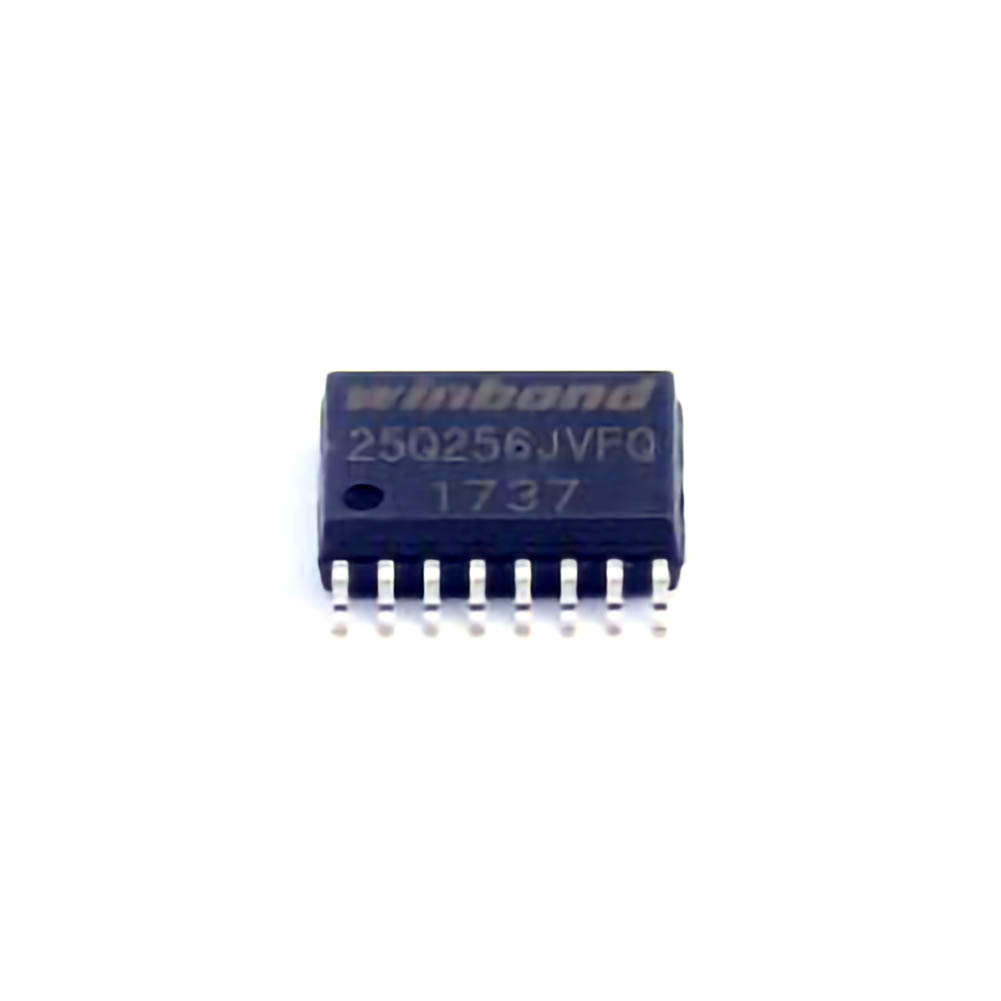
The W25Q128FVSIG is a 128 Mb (16 MB) serial flash memory component designed for use in embedded systems, including IoT devices, automotive applications, and consumer electronics. It utilizes a SPI (Serial Peripheral interface ) for high-speed data transfer and is known for its reliability and performance. However, like any sophisticated electronic component, the W25Q128FVSIG can experience issues in various stages of its lifecycle, from development to deployment.
Before diving into troubleshooting, it's essential to have a solid understanding of the W25Q128FVSIG's key features:
Capacity and Density: With a storage capacity of 128 Mb (16 MB), the chip is capable of storing a considerable amount of data in a compact form.
SPI Interface: This memory operates over the SPI protocol, which offers fast and reliable data transfer between the flash memory and microcontrollers or processors.
Data Retention and Endurance: The W25Q128FVSIG provides reliable data retention for up to 20 years and supports around 100,000 program/erase cycles.
Common Issues
SPI Communication Failures:
One of the most common issues encountered with the W25Q128FVSIG is communication failures between the flash memory and the host controller. These failures often manifest as incomplete or incorrect data transfer, causing the system to malfunction. The root cause can be a misconfigured SPI interface or faulty wiring.
Possible Causes:
Incorrect Clock frequency or timing settings for the SPI interface.
Insufficient voltage levels or unstable Power supply affecting the memory chip.
Incorrect chip-select (CS) handling or wiring issues leading to communication loss.
Data Corruption or Inconsistent Reads:
Data corruption can occur when the stored data becomes inconsistent or erroneous. This issue may cause the system to read unexpected values from memory, affecting performance and functionality.
Possible Causes:
Write/Erase operations not completing properly due to power instability.
Errors during data programming, especially in high-density regions of memory.
Faulty software or firmware causing improper read/write commands.
Write/Erase Failures:
Write or erase failures are another common problem with flash memory devices. These failures can prevent the W25Q128FVSIG from storing new data or updating existing data, leading to functionality issues.
Possible Causes:
The memory has exceeded its endurance limit (though this is rare in typical usage scenarios).
Incorrect erase command usage or failure to properly enable the write operations.
Hardware problems such as poor solder joints or issues with the PCB that affect the write/erase signals.
Power Supply Issues:
Flash memory devices like the W25Q128FVSIG are sensitive to power fluctuations. Inconsistent voltage or unstable power rails can cause issues such as data corruption, SPI communication failures, and general instability.
Possible Causes:
Insufficient or unstable power supply to the memory chip.
Noise or interference on the power line.
Incorrect voltage levels supplied to the chip, leading to erratic behavior.
Troubleshooting and Solutions
To resolve the above issues effectively, it’s important to take a structured approach to troubleshooting. Below are the recommended steps for diagnosing and addressing common problems with the W25Q128FVSIG.
1. Diagnosing SPI Communication Failures
SPI communication problems are often related to incorrect setup or hardware faults. To troubleshoot, follow these steps:
Check SPI Configuration: Ensure that the SPI bus settings (clock polarity, phase, and frequency) match the requirements of the W25Q128FVSIG. Refer to the datasheet for the correct settings. Typically, SPI mode 0 (CPOL=0, CPHA=0) is used for the W25Q128FVSIG, but your system configuration may vary.
Verify Clock and Chip Select Signals: Use an oscilloscope or logic analyzer to check the SPI clock signal (SCK) and chip select (CS) signals. Ensure the clock frequency is within the device’s specified range (up to 104 MHz for the W25Q128FVSIG). If the CS line is not being asserted or the clock is unstable, communication will fail.
Check for Noise: External noise on the SPI lines can cause data corruption. Make sure the signal integrity is good, and consider using termination resistors or shielding to reduce noise.
Inspect the Power Supply: Ensure the W25Q128FVSIG is receiving a stable power supply. Use a multimeter to check for voltage fluctuations or power drops that could affect communication.
2. Fixing Data Corruption or Inconsistent Reads
If your system reads incorrect or corrupted data from the W25Q128FVSIG, take the following steps:
Ensure Proper Data Programming: When programming data to the flash memory, make sure the write and erase operations are correctly performed. Follow the recommended sequence from the datasheet to ensure proper programming, and always check for any failure flags that may indicate a problem during the write or erase process.
Power-Up Sequence: If the device is not powered up in the correct sequence, it may fail to initialize properly, causing data corruption. Ensure that the W25Q128FVSIG is powered up in accordance with the datasheet recommendations, including appropriate voltage ramp-up times.
Test with Known Good Data: Use test patterns (e.g., all 1s or all 0s) to verify if the issue is related to specific data patterns or the entire memory.
Check Firmware/Software: Examine the firmware or software that interfaces with the flash memory. Incorrect read/write commands or timing issues in the software could cause the memory to behave unpredictably. Ensure the firmware is compatible with the W25Q128FVSIG and properly handles memory operations.
3. Addressing Write/Erase Failures
To resolve issues with write or erase failures, consider these diagnostic tips:
Check for Endurance Limits: While flash memory is designed to endure 100,000 program/erase cycles, this can be a factor in high-write environments. Use wear leveling techniques to evenly distribute write/erase cycles across the memory.
Verify Write Enable Command: Ensure that the correct write enable (WREN) command is issued before any write or erase operation. Failure to issue this command can result in failed operations.
Use Correct Erase Commands: There are various erase commands, such as chip erase, sector erase, and block erase. Ensure that you are using the correct erase command for the intended operation and that the address ranges align with your memory layout.
Examine Hardware Connections: Inspect the physical connections, particularly the chip-select line and any power or ground issues. A poor connection could prevent the device from properly receiving the write/erase commands.
4. Power Supply Troubleshooting
Power issues can cause a wide range of problems with flash memory, including communication failures and data corruption. To ensure stable operation:
Check Voltage Levels: The W25Q128FVSIG requires a supply voltage of 2.7V to 3.6V. Use a voltmeter to confirm that the supply voltage falls within this range. If the voltage fluctuates, consider adding decoupling capacitor s or using a more stable power supply.
Inspect Grounding: Grounding issues can lead to noise or instability. Ensure that all grounds are connected properly, and that the PCB layout minimizes the potential for ground loops or other interference.
Power Filtering: Add appropriate capacitors near the power pins to filter out any noise or spikes in the power supply, especially in noisy environments.
By following these troubleshooting steps, you can quickly identify and resolve issues with the W25Q128FVSIG, ensuring the reliable performance of your embedded system. Regular maintenance, careful system design, and close attention to the power supply are key factors in preventing issues and extending the lifespan of the flash memory device.
Partnering with an electronic components supplier sets your team up for success, ensuring the design, production, and procurement processes are quality and error-free.


