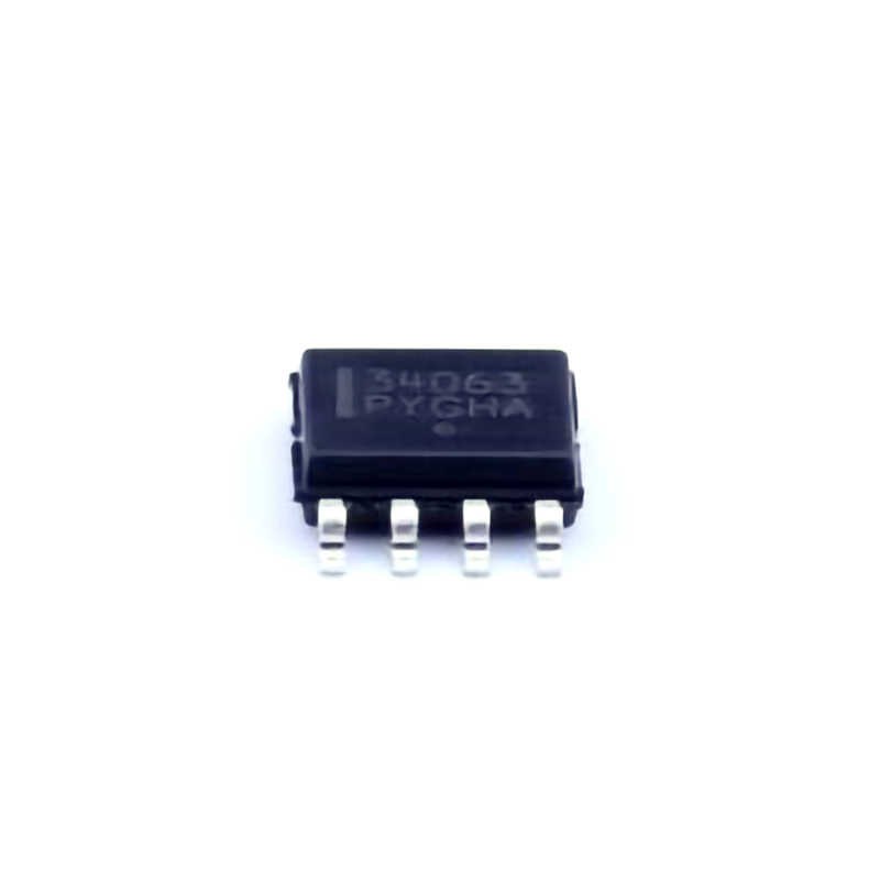
Introduction to MC34063ADR2G and Common Issues
The MC34063ADR 2G is a popular, compact, and highly efficient DC-DC converter integrated circuit (IC) that can operate as a step-up, step-down, or inverting converter. Manufactured by ON Semiconductor, it is widely used in electronic applications for voltage regulation, especially where space and efficiency are important.
Despite its broad application range, users may face some challenges when using this IC, which could lead to performance degradation or failure. In this section, we will explore common issues that can arise during the design and operation of circuits using the MC34063 ADR2G and suggest solutions for troubleshooting.
1. Incorrect Component Selection and Placement
The MC34063ADR2G’s performance heavily depends on external components such as Inductors , Capacitors , and Resistors . A mismatch in component values or improper component placement can lead to malfunctioning circuits. For instance, selecting an incorrect inductor value or an unsuitable capacitor can result in poor voltage regulation, inefficient Power conversion, or noise interference.
Solution:
Inductors: The inductance value plays a crucial role in determining the switching frequency and energy storage within the converter. Ensure that the inductor’s inductance is within the recommended range (typically 100µH to 1mH) and that it can handle the peak current without saturation.
Capacitors: For smoothing output voltage, use low ESR (Equivalent Series Resistance ) capacitors with suitable voltage ratings. Additionally, ensure the values of input and output capacitors are in line with the recommended values in the datasheet to prevent instability and poor filtering.
Resistors: Verify that the resistors used for setting the feedback and switching control are accurate and within tolerance. Incorrect resistor values can lead to improper voltage regulation and efficiency loss.
2. Insufficient Input Voltage
Another common issue that users face with the MC34063ADR2G is insufficient input voltage for the desired output. This problem often occurs when the input voltage is close to or below the minimum operating voltage for the IC.
Solution:
Check the Input Voltage: The MC34063ADR2G requires a minimum input voltage of 3V. If the input voltage is too low, the IC will fail to operate or may only provide a distorted output. Ensure that the input voltage is higher than the required threshold for the intended output configuration.
Power Supply Considerations: If your power supply is unstable or noisy, this could affect the IC’s performance. It’s essential to use a stable, well-regulated power supply to ensure consistent operation.
3. Overheating and Overcurrent Protection Issues
Excessive heat generation can be another issue when working with the MC34063ADR2G, especially if it’s operating near its maximum current limits. Overheating can damage the IC and affect the overall reliability of your power supply.
Solution:
Thermal Management : The MC34063ADR2G typically operates at a maximum output current of 1.5A. Ensure that the IC’s power dissipation is within safe limits. You can improve thermal management by using heat sinks, proper PCB layout for heat dissipation, and ensuring good airflow around the IC.
Current Limiting: If overcurrent is detected, consider using additional external circuitry to limit the current. Monitoring the output current using a current sense resistor and feedback mechanism can help prevent the IC from operating in an overcurrent state.
4. Noise and Ripple Problems
Another common issue is noise or ripple on the output voltage, which can affect sensitive loads such as microcontrollers or analog circuits. Noise often results from improper filtering or component selection.
Solution:
Capacitor Upgrades: To reduce noise and ripple, consider upgrading the output and input capacitors to higher-quality low-ESR capacitors. Increasing the capacitance slightly may also help with smoothing.
Inductor Selection: Use an inductor with low resistance and a high-quality core to minimize noise generation during switching.
5. Incorrect Feedback Configuration
The feedback loop in the MC34063ADR2G is crucial for regulating the output voltage. If the feedback components (typically resistors) are improperly chosen or misconfigured, the output voltage can drift or be unstable.
Solution:
Check Feedback Network: Ensure that the feedback resistors are correctly placed, and the feedback loop is functioning properly. Use accurate resistors with low tolerance to minimize voltage fluctuations.
Stabilizing the Feedback: Adding a small capacitor in parallel with the feedback resistor may help stabilize the feedback loop and prevent oscillations.
Advanced Troubleshooting and Optimization
In this section, we will delve deeper into advanced troubleshooting techniques for the MC34063ADR2G and discuss optimization strategies to enhance performance.
6. Designing for Efficiency
While the MC34063ADR2G is relatively efficient, its efficiency can degrade in specific configurations, especially if components are not chosen carefully or if the operating conditions are suboptimal.
Solution:
Optimize Inductors and Capacitors: High-quality inductors and capacitors not only help with reducing noise and ripple but can also improve overall efficiency. Ensure that the inductor is rated for high current and low resistance, while capacitors should have a low ESR to minimize power loss.
Switching Frequency Considerations: The switching frequency of the MC34063ADR2G is determined by the timing capacitor. Adjusting the timing capacitor can alter the switching frequency, which can impact efficiency. Typically, a lower switching frequency leads to lower switching losses but may result in larger passive components. Choose the switching frequency to balance efficiency and component size.
7. PCB Layout and Grounding Techniques
A poor PCB layout is one of the most common causes of malfunction or inefficiency in power supply circuits. Proper grounding and layout techniques are essential for ensuring stable performance of the MC34063ADR2G.
Solution:
Minimize Ground Bounce: Ensure that the ground plane is as continuous as possible, with minimal impedance. A solid ground plane can reduce noise and improve stability by providing a low-impedance path for high-frequency currents.
Separate High and Low Current Paths: On the PCB, isolate high-current paths from sensitive control circuitry to avoid coupling noise. Keep the switch and power components away from feedback and control components to reduce interference.
Use of Decoupling Capacitors: Place decoupling capacitors close to the IC’s power supply pins to reduce high-frequency noise and improve the stability of the feedback loop.
8. Troubleshooting the Feedback Loop
The feedback mechanism is vital for ensuring that the output voltage remains stable. If the feedback loop is misconfigured, the IC may oscillate or output incorrect voltages. This issue may not always be obvious, making troubleshooting a bit more challenging.
Solution:
Oscilloscope Testing: Using an oscilloscope to measure the output voltage waveform can help identify oscillations or irregularities in the feedback loop. Look for signs of instability, such as ringing or high-frequency oscillations, which indicate that the feedback loop needs to be stabilized.
Optimize Resistor Values: Fine-tune the feedback resistor values to ensure that they match the desired output voltage. Small adjustments may be required to achieve a stable output, especially in high-load or high-frequency applications.
9. Ensuring Long-Term Reliability
Ensuring the long-term reliability of the MC34063ADR2G in your design is crucial, especially in mission-critical applications.
Solution:
Thermal Cycling: Subject the power supply to thermal cycling tests to ensure that it can withstand temperature variations without performance degradation. Check for solder joint issues and potential component failures.
Component Derating: Derate components to ensure they operate within their safe limits. For instance, avoid operating the IC at the maximum current limit continuously, and ensure that components like capacitors and inductors are not stressed by high ripple currents or voltage spikes.
10. Testing and Iteration
Finally, the most effective way to troubleshoot and optimize the MC34063ADR2G is through rigorous testing and iteration. After building the initial circuit, subject it to a variety of load conditions, and monitor the output voltage and current. Iteratively adjust component values, layout, and design to fine-tune the performance.
Solution:
Load Testing: Apply a variable load to the output and observe the stability of the voltage under different conditions. This will help you identify any issues related to regulation and efficiency.
Simulation Software: Use circuit simulation tools (such as LTspice) to model the circuit and identify potential problems before physically building the circuit.
Conclusion
The MC34063ADR2G is a versatile and reliable IC for DC-DC conversion, but like any power supply component, it requires careful consideration of external components, layout, and operational conditions. By addressing common troubleshooting issues such as incorrect component selection, insufficient voltage, noise, and improper feedback configurations, you can ensure the stable and efficient operation of your power supply circuits. Through diligent testing, optimization, and adhering to best design practices, you can maximize the performance and reliability of your MC34063ADR2G-based circuits.
Partnering with an electronic components supplier sets your team up for success, ensuring the design, production, and procurement processes are quality and error-free.


