Introduction to UCC27524ADR and Common Issues
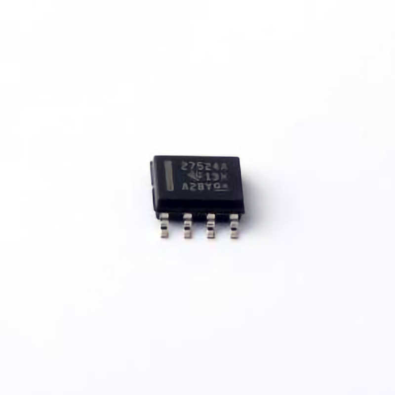
The UCC27524ADR is a high-speed, dual-channel MOSFET driver from Texas Instruments, designed to interface with Power MOSFETs in a variety of applications, including motor drives, power supplies, and inverters. Known for its robust performance, the UCC27524ADR offers features such as low propagation delay, high peak output current, and low output impedance. Despite its reliable design, issues can sometimes arise during implementation, especially when the driver is used in demanding, high-frequency circuits. Troubleshooting these problems can be daunting, but with the right approach, most issues can be quickly identified and resolved.
In this part of the article, we will discuss the key components of the UCC27524ADR driver, common issues you may encounter when using it, and basic diagnostic techniques to begin resolving these challenges.
Understanding the UCC27524ADR Driver
Before delving into troubleshooting, it is important to understand the UCC27524ADR‘s design and functionality. The device is a dual MOSFET driver that can drive both low-side and high-side MOSFETs in half-bridge or full-bridge configurations. It features a low-side driver that can handle up to 4A of peak current and a high-side driver with up to 4A of peak current. The driver supports logic-level inputs and can be easily interfaced with microcontrollers, PWM controllers, or other logic devices.
The key benefits of using the UCC27524ADR in power applications include:
High-speed operation: Low propagation delay (20 ns typical) and high-frequency performance.
High peak output current: Capable of delivering 4A peak output current for both low-side and high-side drivers.
Low output impedance: Ensures minimal losses and efficient switching.
With these features, the UCC27524ADR is well-suited for applications requiring fast switching and efficient drive for power transistor s, such as in motor control, DC-DC converters, and other power electronics circuits.
Common Troubleshooting Scenarios
While the UCC27524ADR is highly reliable, like any component, it can encounter issues during the design and implementation phase. Some of the most common problems engineers may face with the UCC27524ADR include:
Output Drive Issues: No output signal or weak output drive, even though the logic input is present.
Inconsistent Switching: The MOSFETs may switch erratically, resulting in power loss or system instability.
Overheating or Burnout: The driver or MOSFETs may overheat, leading to thermal shutdown or permanent damage.
Voltage Spikes: High-voltage spikes during switching that can damage the components.
Excessive EMI (Electromagnetic Interference): Unwanted noise generated by the switching process.
In the following sections, we will explore the steps to diagnose and address these common issues in greater detail.
Troubleshooting Step-by-Step
1. No Output Signal / Weak Output Drive
If you notice that there is no output or that the output is weak or inconsistent despite applying the expected input signals, the first thing to check is the power supply. Ensure that the UCC27524ADR has sufficient supply voltage (typically 10V to 20V) and that it is within the specified range. A low or fluctuating supply voltage can cause weak output or complete failure to drive the MOSFET.
Next, verify the input signal integrity. If the logic input voltage is not within the specified limits for the UCC27524ADR (typically 3V to 15V for high-level input), the driver will fail to switch properly. Using an oscilloscope, check both the input signal and the output signal to ensure that the driver is receiving the correct input and that the output waveform is appropriate.
Also, inspect the output impedance of the driver. A high output impedance could indicate an issue with the driver’s output transistors or a fault in the PCB layout, such as poor grounding or power routing.
Solution: If the problem persists, consider replacing the MOSFET or the driver itself to rule out hardware failure. Additionally, check the thermal conditions (e.g., inadequate heatsinking) to prevent damage to the components.
2. Inconsistent Switching or Erratic Behavior
Inconsistent switching behavior can be the result of several factors, such as insufficient gate drive, improper gate resistors, or Timing mismatches. If the gate of the MOSFET is not being driven correctly, the device may not fully turn on or off, causing unpredictable behavior.
Start by examining the gate resistor values. The UCC27524ADR requires appropriate gate resistors to ensure smooth switching and to limit the inrush current during MOSFET switching. Incorrect or missing gate resistors can cause ringing or excessive switching noise.
It’s also essential to check the timing of the input signals. Incorrect timing between the low-side and high-side inputs can cause shoot-through current, where both the high-side and low-side MOSFETs conduct simultaneously, leading to short circuits and excessive power dissipation.
Solution: Check for any misalignment in timing signals and ensure that both the high and low drivers are properly synchronized. Adjust gate resistors to match the MOSFETs being used, and use a proper gate driver layout to minimize noise and parasitic effects.
3. Overheating or Burnout
Overheating of the UCC27524ADR or the MOSFETs in the circuit is a serious issue, as it can lead to component failure. Several factors can cause overheating, including excessive switching losses, inadequate cooling, or improper voltage levels.
To troubleshoot overheating, first check the thermal conditions of the circuit. Ensure that the UCC27524ADR is not being driven at excessive frequencies or subjected to high currents beyond its rated limits. Heat sinks, proper PCB Thermal Management , and ensuring that the device is not mounted in a thermally constrained area can help prevent overheating.
Verify that the MOSFETs being used are suitable for the operating conditions (e.g., voltage, current, and switching frequency) and have appropriate thermal ratings. If the MOSFETs are undersized, they could overheat and cause failures that might also affect the UCC27524ADR.
Solution: If overheating is occurring due to excessive switching frequency, consider lowering the operating frequency. Additionally, enhance heat dissipation by using better thermal design techniques, such as adding heat sinks or improving airflow in the system.
4. Voltage Spikes
Voltage spikes are another common issue that can arise when using high-speed MOSFET drivers like the UCC27524ADR. These spikes are typically caused by parasitic inductances in the PCB layout or improper snubbing circuits.
To diagnose voltage spikes, use an oscilloscope to measure the voltage across the MOSFETs during switching. Look for ringing or overshoot that exceeds the voltage ratings of the components. These spikes can damage the MOSFETs or the driver if not properly controlled.
Solution: To mitigate voltage spikes, ensure that your PCB layout has short, low-inductance paths for high-speed signals. Use snubber circuits (a combination of resistors and capacitor s) across the MOSFETs to dampen the ringing. Also, consider adding flyback diodes or other protection circuits to suppress voltage spikes.
5. Excessive EMI (Electromagnetic Interference)
In high-speed switching circuits, EMI is a common byproduct. EMI can interfere with nearby sensitive electronics, leading to system instability or malfunctions. Excessive EMI is often a sign of poor layout design or inadequate shielding.
To troubleshoot EMI issues, check the layout of the high-current paths. Keep the high-speed signal traces as short and direct as possible, and separate them from sensitive analog or control circuits. Additionally, ensure that the power and ground planes are solid and continuous, as poor grounding can lead to noise generation.
Solution: Minimize the loop area for high-current paths and implement proper shielding. Use ferrite beads , filters , or ground planes to reduce EMI in the system.
Advanced Troubleshooting, Prevention, and Best Practices
In Part 1, we discussed basic troubleshooting steps for common issues with the UCC27524ADR. In this section, we will focus on more advanced troubleshooting techniques, design considerations to prevent issues from occurring, and best practices to ensure that your UCC27524ADR-powered circuits run reliably and efficiently.
Advanced Troubleshooting Techniques
While the previous section covered the most common issues, sometimes problems may be more complex and require more advanced diagnostic techniques.
Check for Faulty PCB Layout: A poor PCB layout is often the root cause of many issues in high-speed circuits. Use tools such as layout analysis software to inspect the signal integrity of your design. Pay close attention to the trace width and via sizes for high-current paths. Inadequate power and ground routing can lead to ground bounce or other parasitic effects that can disrupt the driver’s performance.
Use a Current Probe: In cases where you suspect current-related issues, using a current probe on the driver’s output or the MOSFET’s gate can help you detect abnormal current flows. This can help diagnose excessive inrush current, shoot-through currents, or other issues that affect switching performance.
Measure Propagation Delay: If the switching timing of the MOSFETs is not as expected, use an oscilloscope to measure the propagation delay of the UCC27524ADR. Compare the actual timing to the datasheet specifications. Excessive delays can indicate issues with signal integrity or power supply problems.
Design Considerations for Prevention
While troubleshooting can help resolve issues, a proactive approach to design can often prevent problems before they occur. Here are some design considerations to keep in mind:
Use Adequate Decoupling Capacitors : The UCC27524ADR requires stable power supply voltage to operate correctly. Place adequate decoupling capacitors close to the power pins of the device to ensure stable operation and reduce noise.
Optimize Gate Drive Circuitry: The gate drive circuit plays a crucial role in determining the switching performance of your MOSFETs. Ensure that the gate resistors, gate capacitance, and driver timing are optimized for the specific MOSFETs being used.
Proper Thermal Management : Ensure that your design includes proper thermal management, especially in high-power applications. Use thermal vias, heat sinks, and other techniques to dissipate heat from the driver and MOSFETs effectively.
Proper Grounding: Ensure that the UCC27524ADR’s ground connection is well-established and that high-current paths are routed away from sensitive components. Implement solid ground planes to minimize noise coupling and parasitic inductances.
Best Practices for Using UCC27524ADR in Power Applications
Validate Power Supply Voltages: Always verify that your power supply is stable and within the recommended operating range for the UCC27524ADR (typically 10V to 20V). Power supply fluctuations can result in unstable behavior or malfunctioning of the driver.
Check for Proper Signal Timing: Ensure that the inputs to the UCC27524ADR are correctly synchronized and that there is no risk of shoot-through or conflicting signals. Use a dead-time controller if necessary to ensure that the high-side and low-side drivers do not turn on simultaneously.
Use Snubber Circuits: Snubber circuits are essential for mitigating voltage spikes, particularly when switching inductive loads. Use appropriate resistor-capacitor combinations to prevent ringing and protect your components.
Monitor System Performance: Continuously monitor system parameters such as temperature, voltage levels, and switching frequencies during operation. This can help detect early signs of issues and prevent catastrophic failures.
By following these troubleshooting steps and best practices, you can ensure that your UCC27524ADR-based circuits perform optimally and reliably. Proper understanding, diagnosis, and prevention are the keys to solving common issues, enhancing system performance, and achieving long-term success in power electronics applications.
If you’re looking for models of commonly used electronic components or more information about UCC27524ADR datasheets, compile all your procurement and CAD information in one place.
( Partnering with an electronic component supplier) sets your team up for success, ensuring that the design, production and procurement processes are streamlined and error-free. (Contact us) for free today.

