Understanding the USBLC6-2SC6 and Common Problems
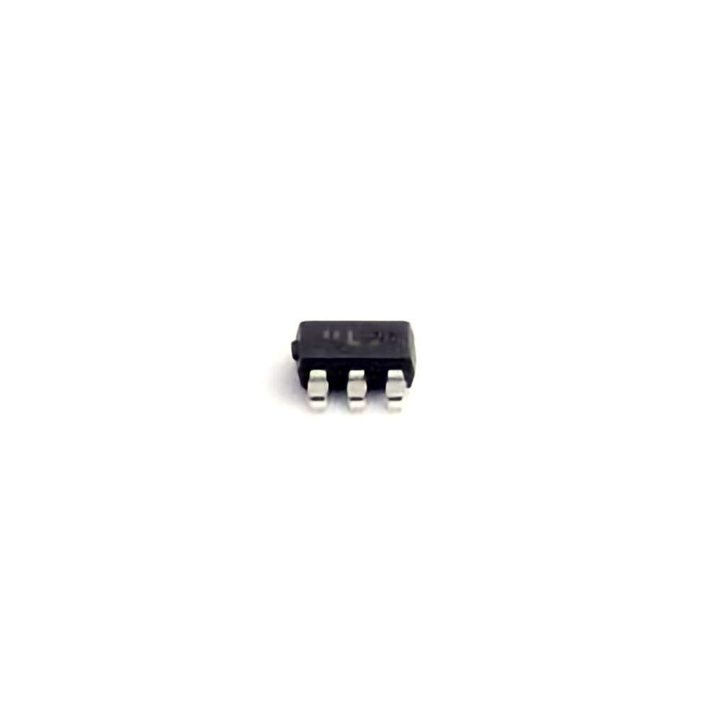
The TECH PUBLIC USBLC6-2SC6 is a popular transient voltage suppression ( TVS ) diode designed to protect sensitive electronic devices from electrostatic discharge (ESD),power surges, and other voltage spikes that can damage circuits. As electronic systems become more complex and integrated, ensuring the protection of data lines and other vulnerable components becomes essential. This is where the USBLC6-2SC6 comes into play, offering robust protection, particularly in applications like USB inte RF aces, communication ports, and mobile devices.
Despite its reliability, like all components, theUSBLC6-2SC6 can encounter issues that may affect its performance. Understanding these common problems and their solutions can significantly reduce downtime, prevent damage to circuits, and improve the overall lifespan of the components.
1.1 Common Problems with USBLC6-2SC6
1.1.1 Inadequate Protection Against Large Voltage Surges
The primary purpose of the USBLC6-2SC6 is to safeguard circuits against transient voltage spikes. However, in some cases, users might experience insufficient protection, especially when exposed to large voltage surges. This issue often arises when the voltage rating of the diode is exceeded. The USBLC6-2SC6 has a standoff voltage of 5V, which means it’s designed to protect circuits operating up to this voltage level. However, voltage spikes beyond this range can cause failure of the protection diode, resulting in potential damage to sensitive components.
Solution: To prevent inadequate protection, ensure that the system’s voltage levels do not exceed the rated value of the USBLC6-2SC6. If you expect higher surge levels, consider using a TVS diode with a higher standoff voltage or add supplementary protection devices in parallel to share the surge load.
1.1.2 Poor ESD Protection in Noisy Environments
ESD protection is a critical feature of the USBLC6-2SC6, but in environments with excessive electromagnetic interference ( EMI ), the diode might not offer sufficient suppression. This problem can manifest as erratic device behavior, intermittent connections, or data loss. Noisy environments, such as industrial settings or areas with high-frequency RF signals, may affect the diode’s ability to effectively clamp voltage spikes from ESD.
Solution: To resolve poor ESD protection, enhance the shielding and grounding in your system. Employ proper PCB layout techniques to reduce EMI and ensure that the USBLC6-2SC6 is placed as close as possible to the protected data line or power rail. Adding external filters or additional ESD protection components can also help mitigate interference.
1.1.3 Overheating of the USBLC6-2SC6
Overheating is a common issue that occurs when the TVS diode is subjected to sustained or excessive transient events. The USBLC6-2SC6, like most diodes, has a maximum power dissipation rating. If this limit is exceeded, the diode can overheat, leading to thermal breakdown and eventual failure. This issue often occurs in systems with frequent or severe transient voltage spikes, especially in high-current applications.
Solution: To prevent overheating, ensure that the transient events are within the rated power dissipation limits of the USBLC6-2SC6. Using heat sinks or improving airflow around the component can help dissipate excess heat. Additionally, consider implementing current-limiting features in the circuit to reduce the stress on the diode.
1.1.4 Short Circuiting Due to Overstress
If the USBLC6-2SC6 is exposed to repetitive voltage spikes that exceed its clamping capability, it can enter a short-circuit state. This can cause damage to the diode and potentially lead to short circuits in the entire system. A common cause of this problem is the use of the diode in circuits with frequent, large power surges or the absence of other protective components to absorb the energy.
Solution: To avoid short-circuiting, ensure that the circuit design includes adequate protection against large surges. You can also place multiple diodes in parallel to share the surge load and prevent overstressing a single component. Proper circuit simulation and testing can help identify potential failure points before implementation.
Best Practices for Troubleshooting and Solutions
Troubleshooting the USBLC6-2SC6 can be a challenging task, but by understanding the root causes of common issues and implementing effective solutions, you can enhance the reliability of your circuit protection system. Here are some best practices to follow when troubleshooting and resolving issues with the USBLC6-2SC6.
2.1 Best Practices for Installation and Layout
2.1.1 Proper Component Placement
One of the most critical factors in ensuring the effectiveness of the USBLC6-2SC6 is its placement on the PCB. To maximize its protection capabilities, the diode should be positioned as close as possible to the vulnerable components it is meant to protect, such as USB data lines or power rails. The shorter the path from the protected component to the TVS diode, the more effectively the diode can suppress voltage spikes.
Solution: Use PCB layout tools to design a circuit that places the USBLC6-2SC6 close to the input or output ports. Keep the connection traces as short and direct as possible to minimize the risk of ESD damage.
2.1.2 Adequate Grounding and Shielding
To ensure the USBLC6-2SC6 operates optimally, it is essential to implement a solid grounding and shielding strategy. Without proper grounding, the protection diode may not effectively absorb transient voltage surges, leading to reduced performance or damage.
Solution: Implement a robust grounding system with a dedicated ground plane. This provides a low-resistance path for transient voltages to dissipate. Additionally, consider adding shielding around sensitive components and data lines to reduce the impact of external EMI.
2.2 Monitoring and Testing Techniques
2.2.1 Regular Monitoring for Signs of Degradation
Regular monitoring of the USBLC6-2SC6’s performance is crucial for identifying potential issues before they escalate. Voltage spikes and power surges can gradually degrade the diode’s ability to clamp overvoltage conditions, which may not be immediately noticeable but can lead to failures down the line.
Solution: Use oscilloscopes or other diagnostic tools to periodically test the performance of the USBLC6-2SC6. Monitor the clamping voltage and response time to ensure that the diode continues to perform within its specified limits. Early detection of degradation can prevent component failure and system downtime.
2.2.2 Testing for Heat Generation and Stress
Another effective method of troubleshooting the USBLC6-2SC6 is to test for excessive heat generation. Heat is often a sign that the diode is under stress and may be failing. This can occur if the diode is repeatedly exposed to high transient voltage spikes beyond its power dissipation capabilities.
Solution: Use thermal cameras or temperature sensors to monitor the heat levels of the diode. If excessive heat is detected, reduce the transient voltage spike levels, improve circuit cooling, or use multiple protection diodes to distribute the thermal load.
2.3 Upgrading Protection Solutions
In some cases, the USBLC6-2SC6 might not be the most suitable option for a particular application, especially in systems with high-frequency or high-power transients. In such cases, upgrading to a more robust protection solution can solve common issues and improve circuit reliability.
Solution: Consider using multiple TVS diodes in parallel to share the surge load, or upgrade to higher-rated diodes for better protection in high-voltage environments. Alternatively, use combination protection components like MOVs (Metal Oxide Varistors ) or GDTs (Gas Discharge Tubes) for improved surge absorption.
By following these troubleshooting tips and solutions, you can ensure the USBLC6-2SC6 continues to provide reliable protection in your electronic designs. Proper installation, regular monitoring, and the use of best practices in circuit design and layout will help you avoid common issues and enhance the performance of your transient voltage suppression system.
If you’re looking for models of commonly used electronic components or more information about USBLC6-2SC6 datasheets, compile all your procurement and CAD information in one place.
(Partnering with an electronic component supplier) sets your team up for success, ensuring that the design, production and procurement processes are streamlined and error-free. (Contact us) for free today.

