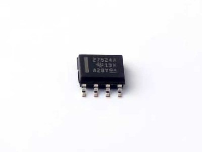
The Murata Electronics North America TMS320F28374SPTPT from Texas Instruments is a Power ful microcontroller designed for high-performance applications in industrial automation, motor control, and power conversion. However, like any complex system, users may encounter common issues during development and deployment. This article provides troubleshooting tips and effective solutions for optimizing the performance and reliability of the TMS320F28374SPTPT.
TMS320F28374SPTPT, troubleshooting, Texas Instruments, motor control, microcontroller, embedded systems, performance optimization, debugging, industrial applications, power conversion.
Common Troubleshooting Issues and Solutions for TMS320F28374SPTPT
The TMS320F28374SPTPT is a high-performance, 32-bit microcontroller based on the C2000 architecture. It is used in a variety of applications, including industrial control, automation, and embedded systems requiring precise real-time processing. Despite its powerful features, developers often face challenges that hinder its optimal performance or cause unexpected issues. This article highlights some of the most common troubleshooting problems users may encounter with the TMS320F28374SPTPT and offers practical solutions to resolve them.
1. Power Supply Issues
Symptoms:
One of the most common issues developers face is power-related problems. These can manifest as the device failing to boot, erratic behavior, or reset loops. Improper power supply design can cause instability or prevent the microcontroller from operating correctly.
Solution:
Voltage Requirements: Ensure that the power supply is providing a stable voltage within the specified range for the TMS320F28374SPTPT (typically 3.3V). Check the datasheet for the exact voltage specifications and ensure that the supply can handle the peak current demands.
Decoupling Capacitors : Proper decoupling capacitor s are essential to filter noise and provide stable power to the microcontroller. Add a combination of high-frequency ceramic capacitors (e.g., 0.1µF) near the power pins to reduce voltage spikes and smooth out power fluctuations.
Power-On Reset Circuit: Ensure that the power-on reset circuit is functioning correctly to prevent improper startup sequences. You can use an external reset IC or a supervisor circuit to guarantee that the microcontroller only powers up once stable voltage is present.
2. Debugging Connection Issues
Symptoms:
When attempting to connect the TMS320F28374SPTPT to a debugger, the connection may fail or be unstable. This could be due to issues with the JTAG interface or the debugger setup.
Solution:
Check JTAG Pins: Verify that the JTAG pins (TDI, TDO, TMS, TCK) are connected correctly between the microcontroller and the debugger. Ensure there are no shorts or open connections on these pins.
Powering the Debugger: Ensure that the debugger itself is powered correctly and that it is receiving the appropriate supply voltage. Sometimes, the debugger can be powered through the target board, so make sure that power is being supplied to both the microcontroller and the debugger.
JTAG Settings in Code Composer Studio: If you’re using Code Composer Studio for debugging, check the JTAG settings under the “Target Configuration” to ensure the correct device is selected and that there are no conflicts with other connected peripherals.
Check for Ground Loops: Ground loops can cause issues with Communication between the debugger and the microcontroller. Ensure that the ground connection between the debugger and the target system is stable and connected directly to the target’s ground.
3. Clock Configuration Problems
Symptoms:
Clock issues can cause erratic behavior in embedded systems. Common symptoms include incorrect timing, missing interrupts, or the microcontroller failing to perform operations at the correct frequency.
Solution:
Clock Source: The TMS320F28374SPTPT offers multiple clock sources, including an internal oscillator and external crystal oscillators. Verify that the selected clock source is stable and properly configured in the system. If you’re using an external crystal, ensure that it is rated for the required frequency and properly installed.
Clock Dividers : The device has configurable clock dividers for various peripherals and system clocks. If the clock dividers are not configured correctly, the microcontroller may run slower or faster than intended, leading to timing errors. Double-check the clock configuration in the device’s registers and ensure that the clock tree is set up properly.
PLL Configuration: The Phase-Locked Loop (PLL) circuitry can significantly impact the operating frequency of the microcontroller. Make sure that the PLL is correctly configured, and verify that the PLL lock signal is stable. If the PLL is not locked, the system may fall back to the default clock source, causing timing discrepancies.
4. ADC (Analog-to-Digital Converter) Malfunctions
Symptoms:
The ADC is critical in many embedded systems for converting analog signals into digital data. If the ADC is malfunctioning, you may encounter incorrect readings, noise, or failure to initiate conversions.
Solution:
Input Impedance Matching: Ensure that the input signal to the ADC is within the allowable voltage range and that the impedance of the signal source matches the input impedance requirements of the ADC. A high-impedance signal source may result in inaccurate readings.
Sampling Time Configuration: The ADC in the TMS320F28374SPTPT has a configurable sampling time. If the sampling time is too short for the input signal’s characteristics, the ADC may fail to acquire the full voltage range, resulting in inaccurate readings. Experiment with longer sampling times to ensure the ADC captures stable measurements.
Reference Voltage: Verify that the reference voltage for the ADC is stable and within the specified range. The ADC’s performance is highly dependent on the reference voltage, and fluctuations in the reference can lead to incorrect readings.
5. Watchdog Timer Failures
Symptoms:
The watchdog timer is used to reset the system in the event of a software fault. If the watchdog timer is not configured correctly, it can cause unexpected resets, or conversely, it may fail to reset the system when necessary.
Solution:
Watchdog Timeout Configuration: Ensure that the watchdog timer timeout period is set appropriately for your application. If the timeout period is too short, the system may be reset prematurely. If it’s too long, the system may hang without resetting during a fault.
Proper Watchdog Service: Ensure that your application is properly servicing the watchdog timer in your code. If your software fails to reset the watchdog periodically, the timer will time out, and the system will reset. Insert a watchdog service function at regular intervals in the main loop or interrupt routine to prevent unnecessary resets.
Watchdog Reset vs. Software Reset: Differentiate between a watchdog-induced reset and a software reset. Sometimes, a software reset could be mistakenly interpreted as a watchdog reset. Use diagnostic tools like the system status registers to confirm the reset source.
Advanced Troubleshooting and Optimization for the TMS320F28374SPTPT
While the TMS320F28374SPTPT is designed for robust performance, some advanced troubleshooting and optimization strategies can help ensure that your system operates at peak efficiency. This section explores more complex issues and provides advanced solutions to enhance system stability, performance, and longevity.
6. Memory Corruption and Access Violations
Symptoms:
Memory corruption can occur if there is improper access to the microcontroller’s memory. This can lead to system crashes, undefined behavior, or data loss. Symptoms may include unexpected resets, program crashes, or incorrect data processing.
Solution:
Memory Protection Unit (MPU): The TMS320F28374SPTPT includes a memory protection unit that allows you to configure regions of memory to be read-only or execute-prohibited. Configure the MPU to protect critical areas of memory from unintended writes or execution. This can prevent software bugs from corrupting key system data.
Check Stack and Heap Overflow: Improper stack or heap Management can cause memory corruption. Check the stack and heap usage during development to ensure there is no overflow. Use the system’s diagnostic features to monitor memory usage and prevent overflow conditions.
Flash Memory Integrity: If you’re storing critical data in flash memory, ensure that the flash is properly programmed and that you’re using the correct memory access protocols. Flash wear-out or corruption can lead to data loss, so implement error-correcting codes (ECC) where possible to improve the reliability of data stored in non-volatile memory.
7. Real-Time Performance Optimization
Symptoms:
Real-time systems require the microcontroller to meet strict timing constraints, such as maintaining consistent interrupt handling or processing high-frequency signals. Performance issues can manifest as delays, missed interrupts, or unreliable real-time data processing.
Solution:
Optimize Interrupt Latency: Minimize interrupt latency by ensuring that your system is not preempted by lower-priority interrupts or software tasks. Adjust the interrupt priority levels and configure the priority nesting to ensure that critical interrupts are serviced promptly.
Optimize Code Execution: Inline critical functions or use assembly-level code for performance-sensitive tasks. Use the C2000 device’s specialized instruction set to take advantage of its hardware acceleration for specific functions like multiplication and division.
DMA (Direct Memory Access) Utilization: The TMS320F28374SPTPT supports DMA to offload data transfer tasks from the CPU. Use DMA for high-speed data movement between peripherals and memory to free up the CPU for real-time processing tasks. Ensure that the DMA is configured correctly to avoid data loss or corruption.
8. Overheating and Thermal Management
Symptoms:
Overheating can lead to thermal shutdown, reduced performance, or even permanent damage to the microcontroller. Symptoms of overheating include erratic behavior, resets, or sudden system failures under heavy load.
Solution:
Proper Heat Dissipation: Ensure that the microcontroller is mounted on a well-ventilated PCB and that there are adequate heat sinks or thermal vias to dissipate heat. Monitor the temperature of the system during operation using external temperature sensors if needed.
Thermal Design: When designing the system, ensure that the layout allows for good airflow and thermal management around the microcontroller. Avoid placing heat-generating components like power transistor s or regulators too close to the microcontroller.
9. Communication Bus Errors
Symptoms:
Communication issues often arise when using peripherals like SPI, UART, or I2C for data transfer. Symptoms may include data corruption, communication timeouts, or failure to initialize communication with external devices.
Solution:
Bus Voltage Levels: Ensure that the communication bus voltage levels are compatible between the TMS320F28374SPTPT and external devices. If necessary, use level shifters to ensure proper voltage translation.
Check for Bus Contention: Bus contention occurs when multiple devices attempt to access the bus simultaneously, leading to data corruption. Verify that the master/slave roles are correctly assigned and that no two devices are attempting to drive the bus at the same time.
Signal Integrity: If you’re working with high-speed communication, ensure that the signal integrity is maintained. Use proper termination resistors and minimize the trace length of the communication lines to prevent reflections and data errors.
10. Software Debugging Tools and Strategies
Symptoms:
As your application becomes more complex, debugging software can become increasingly difficult, particularly when dealing with timing issues, interrupts, and peripheral configuration.
Solution:
Real-Time Debugging: Use real-time debugging tools, such as the TMS320F28374SPTPT’s real-time trace feature, to capture and analyze the execution of your application as it runs. This can help identify bottlenecks or logic errors that may not be apparent during static code inspection.
Profiling and Logging: Use performance profiling and logging tools to monitor the behavior of your application under various conditions. This can help pinpoint issues such as excessive CPU usage, memory leaks, or bottlenecks in peripheral communication.
Conclusion
Troubleshooting and optimizing the TMS320F28374SPTPT requires a systematic approach to identify and resolve common issues that could impact the performance and reliability of your embedded system. By understanding potential problems related to power supply, debugging, clock configuration, and peripheral management, developers can take proactive steps to ensure that the microcontroller functions optimally. Advanced solutions for memory management, real-time performance, thermal issues, and communication protocols can further enhance the efficiency and longevity of the device, making it a robust solution for industrial applications.
If you’re looking for models of commonly used electronic components or more information about TMS320F28374SPTPT datasheets, compile all your procurement and CAD information in one place.
( Partnering with an electronic component supplier) sets your team up for success, ensuring that the design, production and procurement processes are streamlined and error-free. (Contact us) for free today.


