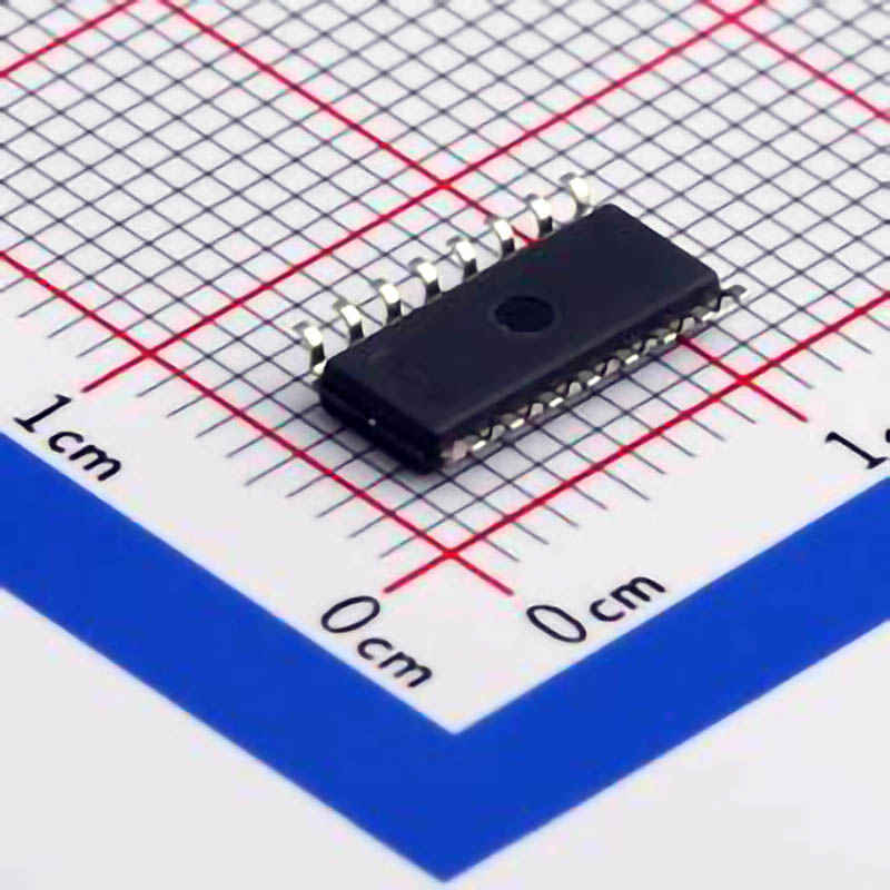
The CD4051BM96 is a widely used analog multiplexer, but like any electronic component, it can encounter issues during use. This article delves into the most common troubleshooting techniques and solutions to keep your circuits running smoothly when working with this versatile device.
CD4051BM96, troubleshooting, analog multiplexer, IC, electronic circuits, debugging, signal switching, multiplexer problems, electronics repair, IC solutions.
Understanding the CD4051BM96 and Identifying Common Problems
The CD4051BM96 is an 8-channel analog multiplexer, designed to route analog or digital signals to a single output based on the logic provided. It is widely used in applications such as signal routing, data acquisition, audio processing, and more. Despite its robust design and versatility, users may encounter various issues that can impact the performance of this multiplexer. Understanding these problems and knowing how to troubleshoot them effectively is essential for any electronics professional or hobbyist working with this device.
1. Power Supply Issues
A very common issue when dealing with ICs like the CD4051BM96 is power supply problems. The device typically operates with a voltage range of 3V to 18V, but variations outside of this range can cause malfunction.
Symptoms:
No output from the multiplexer
Erratic signal behavior
Troubleshooting Tips:
Check the voltage levels at VCC and GND pins to ensure they are within the recommended operating range.
Use a multimeter to measure the supply voltage and compare it against the datasheet specifications.
If the power supply fluctuates or is unstable, try using a regulated power source.
2. Incorrect Control Logic
The CD4051BM96 uses a 3-bit binary control signal (S0, S1, S2) to select one of the eight channels. If these control signals are incorrectly configured, the multiplexer will not route the input signals properly.
Symptoms:
The wrong channel is selected
No signal is passed through
Troubleshooting Tips:
Ensure that the control pins (S0, S1, S2) are connected correctly to the logic source (e.g., microcontroller or switches).
Check the logic level of each control pin to ensure they are within the expected HIGH or LOW voltage levels. For example, S0 should be HIGH for certain channels and LOW for others.
Use a logic analyzer or oscilloscope to verify the timing and correctness of the control signals.
3. Grounding Problems
Improper grounding can lead to unexpected behavior in many integrated circuits, including the CD4051BM96.
Symptoms:
Unstable or noisy output signals
No signal at all
Troubleshooting Tips:
Double-check the GND pin connection to ensure it is properly grounded.
If your circuit shares a ground with other components, ensure that the ground connection is solid and there are no ground loops.
A floating ground can sometimes cause erratic behavior; connecting the GND pin to the common ground plane is critical.
4. Signal Integrity Issues
The CD4051BM96 is capable of switching both analog and digital signals, but the quality of the input signals plays a crucial role in the output performance. Analog signals, in particular, are susceptible to noise and distortion if the multiplexer is not used properly.
Symptoms:
Distorted output signal
Noise or hum in the output signal
Troubleshooting Tips:
Use proper decoupling capacitor s near the VCC and GND pins to reduce noise.
Ensure that the input signal is within the acceptable voltage range and that it does not exceed the VCC levels.
When working with high-frequency signals, ensure that the traces are kept as short as possible to minimize signal degradation.
5. Overloading of Inputs
The CD4051BM96 can switch multiple analog signals, but it has limitations regarding the voltage levels and the current that can be safely applied to each input channel. Overloading an input pin can cause the device to malfunction or even be damaged.
Symptoms:
The multiplexer fails to select certain channels
The IC heats up or behaves erratically
Troubleshooting Tips:
Ensure that the input voltage on any channel does not exceed the power supply (VCC) or fall below the ground potential.
Check if any input signals are excessively high in voltage or current; using resistors or buffers can help protect the IC.
If you're working with analog signals, ensure that they are within the specified range to prevent damage.
Advanced Troubleshooting Techniques and Solutions
Once the basic issues have been addressed, it's important to dive into more advanced troubleshooting strategies for the CD4051BM96. These methods can help identify subtle problems that might not be immediately obvious.
1. Signal Routing Confusion
At times, the expected output channel might not align with the control signals due to a miscommunication or software error. This issue can occur in complex systems where the control signals are dynamically set, such as in microcontroller-based designs.
Symptoms:
Channel selection doesn't match the control inputs
Expected signal routing doesn’t occur
Troubleshooting Tips:
Check if the logic signals from the controlling device are stable and correctly timed.
If you're using software to drive the control signals, ensure that the correct values are being sent at the right times.
A mismatch between the expected and actual control signals can sometimes be detected by monitoring the control lines with an oscilloscope.
2. Delays in Switching
One of the unique features of the CD4051BM96 is its ability to quickly switch between multiple channels. However, if there’s a delay in the switching process, it could cause issues, particularly in time-sensitive applications.
Symptoms:
Delay between control signal change and output signal change
Glitches or artifacts during switching
Troubleshooting Tips:
Ensure that the S0, S1, S2 control signals are stable before making the switch.
Use a slow enough clock signal if you are switching channels sequentially, and verify that the switching timing matches the datasheet recommendations.
In some cases, placing small capacitors on the control lines can help stabilize transitions, although this should be done with caution to avoid affecting the signal integrity.
3. IC Overheating
ICs like the CD4051BM96 are designed to handle specific levels of current and heat dissipation. However, pushing the IC beyond its limits in terms of voltage, current, or improper use can cause it to overheat, leading to failure.
Symptoms:
IC becomes hot to the touch
Signal output becomes unreliable or disappears entirely
Troubleshooting Tips:
Check the datasheet for the maximum current and power dissipation specifications.
Ensure that the device is not operating outside of its recommended voltage or current range.
Use a heat sink or increase the airflow around the IC if you're operating it near its maximum ratings.
Use thermal imaging or an infrared thermometer to identify any hot spots on the IC.
4. Dealing with Unwanted Crosstalk
When working with multiplexers like the CD4051BM96, crosstalk between channels can sometimes occur, especially if the signals are noisy or improperly routed.
Symptoms:
Unwanted signals appear on inactive channels
Channels seem to bleed into each other
Troubleshooting Tips:
Increase the physical distance between the input channels to reduce coupling.
Shield the multiplexer from external noise by using proper grounding and placing it in a shielded enclosure.
Adding bypass capacitors between the channels can help reduce the effects of crosstalk.
5. Replacing a Damaged IC
After performing all troubleshooting and finding no resolution, it's possible that the IC itself may have been damaged. If the CD4051BM96 is no longer functioning correctly, replacing the IC might be the best course of action.
Symptoms:
IC shows no response to input or control signals
The IC is physically damaged (e.g., burnt smell, discoloration)
Troubleshooting Tips:
If you suspect the IC is damaged, first check all the surrounding components to ensure that none of them are shorted or damaged.
Consider using a replacement IC from a reputable source to ensure quality and proper functionality.
In conclusion, the CD4051BM96 is a highly reliable multiplexer for routing analog and digital signals, but like any electronic component, it can face issues during use. By following these troubleshooting strategies, you can solve most problems quickly and get your circuit back on track. Remember, careful inspection, proper setup, and taking preventive measures can significantly reduce the chances of encountering these issues in the first place.
Partnering with an electronic components supplier sets your team up for success, ensuring the design, production, and procurement processes are quality and error-free.


