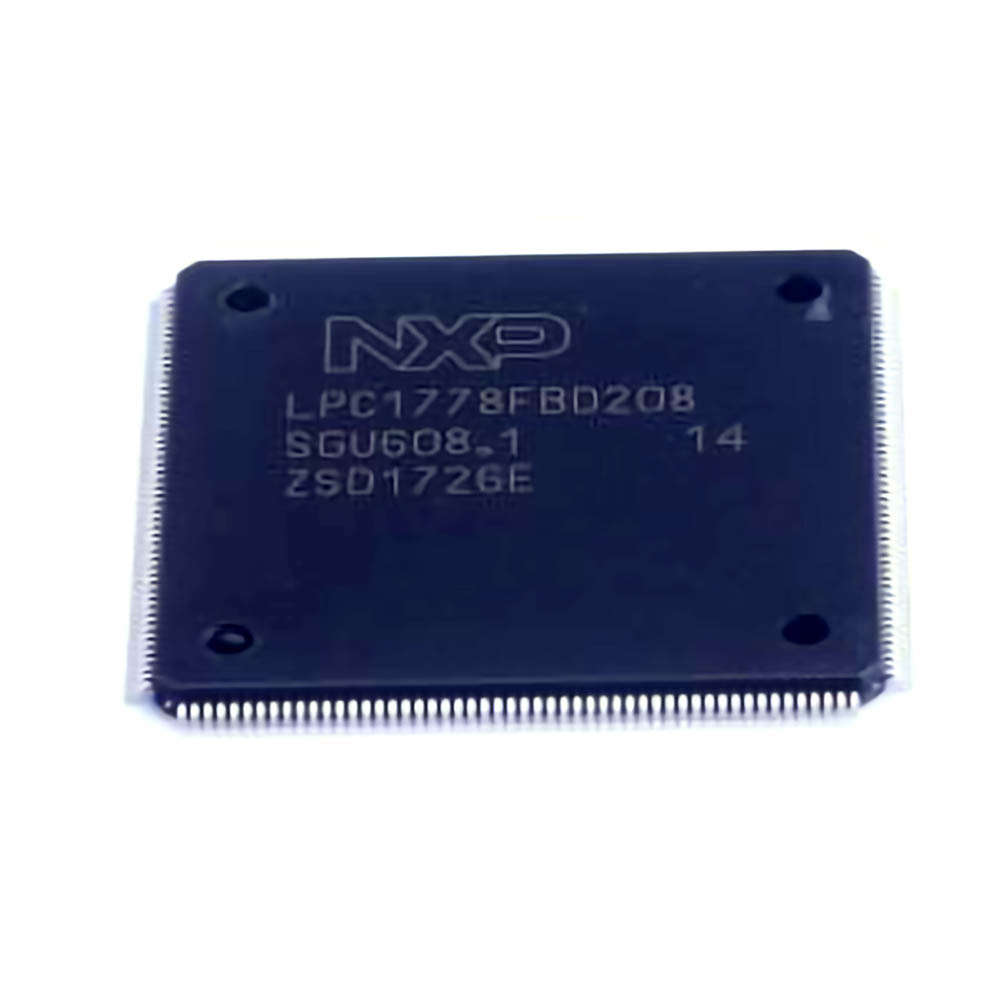
Identifying Common Issues with the LPC1778FBD208 Microcontroller
The LPC1778FBD208 is a high-performance microcontroller from NXP, designed for embedded applications in industrial, consumer, and automotive devices. With its advanced ARM Cortex-M3 architecture, rich peripheral set, and low Power consumption, it offers significant advantages for system designers. However, like any piece of technology, it is prone to occasional issues, whether from hardware setup or software configuration. Identifying and solving these problems early on can save considerable time, enhance performance, and reduce the risk of long-term failures.
1. Power Supply Issues
One of the most frequent problems faced by developers working with the LPC1778FBD208 microcontroller is power supply instability. The LPC1778FBD208 requires a stable 3.3V power input for reliable operation. A voltage drop, noise, or fluctuations in the power supply can lead to erratic behavior, such as unexpected resets, incomplete code execution, or peripheral malfunction.
Solution: Ensure that the power supply is regulated and capable of providing a stable 3.3V. A decoupling capacitor (typically 100nF) placed close to the VCC pin can help filter out high-frequency noise and stabilize the voltage. Additionally, using a power supply with proper filtering and low output ripple can drastically improve the system’s stability.
2. Clock Configuration Problems
Another issue developers frequently encounter is improper clock configuration. The LPC1778FBD208 operates using an external crystal oscillator or an internal RC oscillator, both of which need to be configured correctly in the firmware. A misconfigured clock source or clock frequency can lead to slow operation, system instability, or failure to start.
Solution: Check the clock source settings in the system control block and ensure the correct external oscillator is selected if used. Make sure the clock frequency is set according to your application requirements. It’s also essential to verify the crystal or external oscillator’s specifications, ensuring they match the controller’s supported frequency range.
3. Inadequate Peripheral Initialization
Peripherals are an essential part of any microcontroller, and the LPC1778FBD208 offers many, such as UART, SPI, I2C, ADC, and GPIOs. Incorrect initialization of these peripherals can result in failures in Communication , incorrect sensor readings, or unresponsive systems.
Solution: Review your initialization code for all peripherals. Make sure that each peripheral’s settings (e.g., baud rate, pin direction, clock source) are correct. If using libraries or middleware, ensure that the peripheral initialization sequence is followed in the right order. Additionally, always check the microcontroller’s datasheet for specific initialization requirements.
4. Boot Mode Confusion
Another frequent issue developers face is boot mode misconfiguration. The LPC1778FBD208 microcontroller has different boot modes, such as serial bootloader, ISP, and application boot modes. If the boot mode is not set correctly, the system may fail to load the user application or enter a non-functional state.
Solution: Ensure that the boot mode pins are configured correctly at startup. This configuration can be adjusted through the pins connected to the microcontroller’s Boot ROM. The default boot mode can be changed to suit the application by toggling these pins during power-up or reset. Double-check the microcontroller’s datasheet for the appropriate pin settings for the desired boot mode.
5. Debugging Connection Issues
Debugging issues are common in embedded systems development. The LPC1778FBD208 supports various debugging methods, including JTAG and SWD (Serial Wire Debug). However, poor connections or incorrect debugging configurations can prevent the debugger from connecting to the microcontroller.
Solution: First, check the physical connections of the JTAG or SWD interface . Ensure that all pins are securely connected to the debugger or programmer. If using SWD, ensure that the required 3.3V, SWDIO, SWCLK, and GND pins are correctly wired. Additionally, verify the firmware settings, as certain pins may need to be configured for debugging purposes.
6. Firmware or Software Corruption
Corruption of the firmware is a serious issue, often caused by improper flashing of the microcontroller, power loss during the flashing process, or programming bugs. This issue can result in the microcontroller failing to execute the user application or entering a dead state.
Solution: If firmware corruption is suspected, attempt to reflash the microcontroller using a proper flashing tool or bootloader. If necessary, erase the entire flash Memory before reprogramming. Always ensure that the programming process is uninterrupted, and consider using a power supply with a battery backup or a UPS during programming to avoid power loss.
Advanced Troubleshooting and Performance Optimization for LPC1778FBD208
While identifying and fixing common issues is crucial, optimizing the performance of the LPC1778FBD208 can ensure a smooth user experience and enhance the system’s longevity. Let’s dive into some advanced troubleshooting techniques and strategies for boosting performance.
7. Handling Interrupts and Timing Issues
Interrupt handling is one of the cornerstones of embedded systems, and improper handling of interrupts can lead to system failures or unexpected behavior. The LPC1778FBD208 provides various interrupt sources, and managing them efficiently is key to reliable operation.
Solution: Ensure that interrupts are properly prioritized and that interrupt service routines (ISRs) are short and efficient. Long ISRs can block other critical interrupts, leading to timing issues. Furthermore, verify that all interrupt flags are cleared at the appropriate times, and no interrupt is missed due to incorrect interrupt handling.
8. Watchdog Timer Misconfigurations
The watchdog timer is an essential tool for recovering from system lock-ups or crashes. If the watchdog timer is not configured correctly, it can either fail to reset the system in case of a malfunction or reset the system prematurely.
Solution: Review the watchdog timer configuration to ensure it is set to a reasonable timeout value, appropriate for your application. Set the watchdog reset to trigger only in the event of system hang or failure, and make sure that the timer is regularly refreshed during normal operation. The watchdog should act as a last line of defense and not interfere with the system under normal conditions.
9. Memory Management Problems
Efficient memory management is critical for systems with limited RAM and flash memory, such as those running on the LPC1778FBD208. Inefficient memory allocation or leaks can lead to crashes or performance degradation.
Solution: Use the available memory wisely. Optimize the heap and stack sizes, and make sure that memory is allocated and deallocated properly. Tools like memory profilers can help identify areas where memory is being inefficiently used. Additionally, keep an eye on the available flash memory and periodically review firmware code to remove unnecessary code and functions.
10. System-Level Performance Tuning
To optimize the overall performance of the LPC1778FBD208 system, it’s essential to consider system-level tuning. This includes fine-tuning clock settings, optimizing software algorithms, and configuring peripherals for power efficiency.
Solution: Adjust clock frequencies to match the application’s processing requirements. For power-sensitive applications, consider using the LPC1778FBD208’s low-power modes when the system is idle. Additionally, optimize software algorithms to reduce CPU usage and improve the overall responsiveness of the system. Make sure to use hardware peripherals wherever possible to offload tasks from the CPU.
11. Ensuring Robust Communication
Communication between the microcontroller and other devices is a critical aspect of most embedded systems. The LPC1778FBD208 offers various communication interfaces like SPI, I2C, and UART, which are often sources of communication errors if not configured properly.
Solution: Ensure that baud rates, clock settings, and peripheral configurations match on both ends of the communication link. Implement error checking mechanisms such as checksums or cyclic redundancy checks (CRC) to detect and handle communication errors. If using I2C, ensure proper pull-up resistors are used on the SDA and SCL lines to ensure reliable data transmission.
12. Leveraging DMA for Efficient Data Handling
Direct Memory Access (DMA) is an essential feature for optimizing data transfers, especially when dealing with large data volumes. If used incorrectly, however, DMA can lead to data corruption or excessive CPU overhead.
Solution: Set up DMA transfers carefully, ensuring that the source and destination addresses are valid and that the transfer size matches the available memory. Use DMA with peripherals like ADC, DAC, and UART to reduce CPU load and improve throughput. Also, ensure that the DMA interrupt is handled properly to monitor the completion of data transfers.
In conclusion, troubleshooting the LPC1778FBD208 involves understanding both hardware and software configurations. By addressing power supply issues, clock misconfigurations, and peripheral initialization problems, users can prevent common pitfalls. Advanced techniques such as efficient memory management, proper interrupt handling, and leveraging DMA can further optimize system performance. With careful attention to these areas, the LPC1778FBD208 can deliver reliable and efficient performance for a wide range of embedded applications.
If you’re looking for models of commonly used electronic components or more information about LPC1778FBD208 datasheets, compile all your procurement and CAD information in one place.
( Partnering with an electronic component supplier) sets your team up for success, ensuring that the design, production and procurement processes are streamlined and error-free. (Contact us) for free today.

