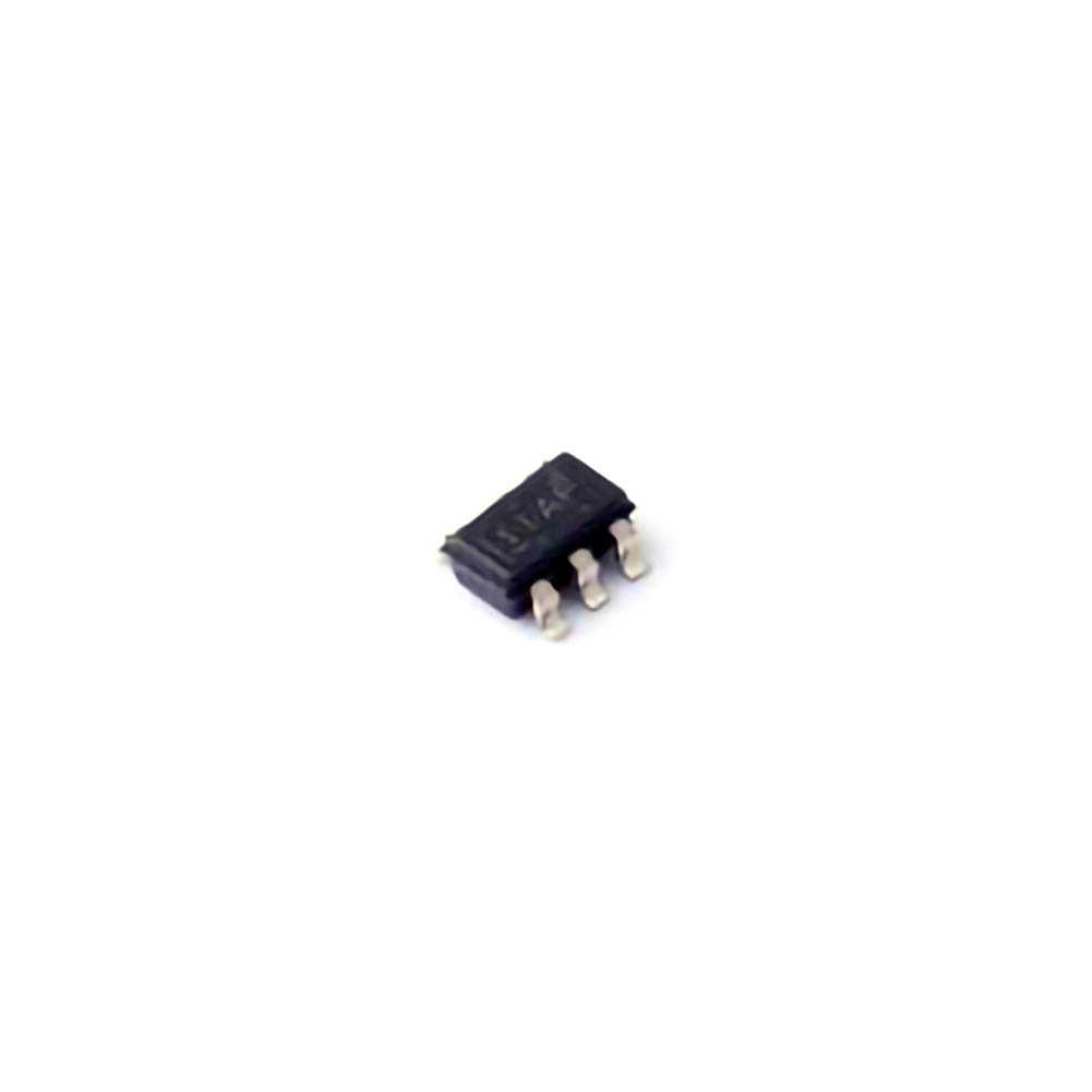
The TPS22917DBVR is a popular Power load switch used in various electronics applications to control power distribution. However, like any other s EMI conductor device, it is not immune to failure, especially when operating under certain stress conditions. This article explores the common causes of TPS22917DBVR power load failure and provides effective solutions to mitigate these issues. With a focus on both practical troubleshooting and design best practices, this guide is invaluable for engineers and technicians working with load switches in power Management systems.
TPS22917DBVR, power load failure, power load switch, troubleshooting, electronic design, power management, semiconductor failure, load switch issues, component protection
Understanding TPS22917DBVR Power Load Failure
In today’s rapidly evolving electronics market, ensuring reliable and efficient power management is paramount for product performance. The TPS22917DBVR, a power load switch from Texas Instruments, is a key component used to manage and protect circuits by controlling power distribution. This power load switch features overcurrent protection, low on- Resistance , and robust thermal performance, making it ideal for various applications in consumer electronics, industrial systems, and portable devices. However, despite its advanced features, like any other semiconductor, the TPS22917DBVR can experience failure under certain conditions.
What Is a Power Load Switch?
A power load switch, such as the TPS22917DBVR, serves as a key element in regulating the flow of power within a circuit. It essentially acts as an electronic relay that can turn power on or off to various parts of the system. Load switches are commonly used in applications requiring the management of power to multiple devices without adding significant complexity or power loss.
The TPS22917DBVR is particularly known for its low on-resistance, which means it offers minimal voltage drop across the switch when it is in the "on" state. This reduces the amount of heat generated and ensures that the power distribution is as efficient as possible. The device also includes built-in protection features, including overcurrent protection and thermal shutdown, which help safeguard the system in the event of electrical faults.
Common Causes of TPS22917DBVR Power Load Failure
Though the TPS22917DBVR offers robust protection and control features, certain conditions can lead to power load failure. Understanding these potential failure modes is crucial for troubleshooting and ensuring long-term reliability in system designs.
1. Overcurrent Conditions
Overcurrent is one of the most common causes of power load switch failure. When the current drawn by the load exceeds the safe operating limits of the TPS22917DBVR, it can lead to a failure of the switch, causing it to malfunction or shut down entirely. The TPS22917DBVR is equipped with built-in overcurrent protection, but it may not be able to handle extremely high or prolonged overcurrent conditions. If the load current exceeds the switch’s maximum rated current for an extended period, it can damage internal components or trigger thermal shutdown.
2. Incorrect PCB Layout
The layout of the printed circuit board (PCB) plays a crucial role in the performance and reliability of the TPS22917DBVR. Poor PCB design can lead to issues such as excessive trace resistance, inadequate decoupling, or improper grounding, all of which can affect the power load switch’s performance. For example, long or narrow traces can increase the voltage drop and cause excessive heating, leading to potential failure.
3. Inadequate Thermal Management
The TPS22917DBVR has thermal protection built into its design, but it is still susceptible to overheating if the system does not have adequate cooling. Factors such as poor heat dissipation, lack of proper thermal vias, and insufficient copper area for heat spreading can result in higher junction temperatures, which may trigger thermal shutdown or permanent damage to the switch.
4. ESD (Electrostatic Discharge) Damage
Like most semiconductor devices, the TPS22917DBVR is sensitive to electrostatic discharge (ESD). Improper handling during the assembly or installation process can result in ESD damage, which can cause a permanent failure of the switch. ESD-induced failures are particularly dangerous because they may not immediately show up in normal operation but can lead to latent failures that degrade the device over time.
5. Inrush Current
When powering up a system, especially those with large capacitive loads, inrush current can occur. This is a short burst of high current that happens when the system is initially powered on. If the inrush current exceeds the switch’s current-limiting capabilities, it can trigger an overcurrent event, potentially causing the TPS22917DBVR to shut down or fail.
6. Voltage Spikes and Transients
The TPS22917DBVR has integrated overvoltage protection, but severe voltage spikes or transients, such as those caused by inductive loads or switching transients, can still damage the device. In cases where there are large voltage spikes or surges beyond the device's rated voltage range, the internal circuitry can be damaged, leading to a failure.
7. Incorrect Input or Output capacitor Values
The use of incorrect or inadequate input and output Capacitors can affect the performance of the power load switch. If the capacitor values are too low, the switch may not operate stably, leading to oscillations, noise, or even thermal overload. Conversely, excessive capacitance can lead to higher inrush currents, exacerbating the potential for overcurrent conditions.
Symptoms of Power Load Failure in TPS22917DBVR
Recognizing the signs of power load failure early can prevent further damage to the circuit and improve system reliability. Common symptoms of TPS22917DBVR failure include:
Unstable Power Output: The system may experience fluctuations or complete loss of power to downstream components.
Overheating: If the switch is damaged or operates under thermal stress, it may overheat and shut down.
Erratic Behavior: If the switch is intermittently switching on and off, it could be indicative of internal damage or poor PCB layout.
Current Limiting: If the TPS22917DBVR is experiencing overcurrent conditions, it may continuously limit current, preventing proper operation.
Solutions and Preventative Measures for TPS22917DBVR Power Load Failure
Having explored the common causes of TPS22917DBVR power load failure, the next step is to look at effective solutions and design best practices to mitigate these issues. By understanding the root causes of failure and implementing preventive measures, engineers can ensure that their power load switches operate reliably and efficiently.
1. Design for Proper Current Handling
One of the most effective ways to prevent overcurrent-related failure is to carefully match the TPS22917DBVR with the appropriate load. Ensure that the current drawn by the load never exceeds the maximum current rating of the switch. For applications with varying load conditions, consider using a current sensing circuit to monitor real-time current and dynamically adjust power delivery.
To further safeguard against overcurrent, use fuses or circuit breakers in series with the load to provide an additional layer of protection. These components can disconnect the circuit in case of sustained overcurrent, preventing damage to the load switch.
2. Optimize PCB Layout
A well-designed PCB layout is essential for ensuring reliable performance of the TPS22917DBVR. Key design guidelines include:
Minimize Trace Resistance: Use wide traces with low resistance to reduce voltage drop and prevent excessive heating.
Place Decoupling Capacitors Close to the Switch: Use capacitors with appropriate values close to the input and output pins of the TPS22917DBVR to reduce noise and voltage fluctuations.
Ensure Proper Grounding: A solid ground plane with low impedance helps reduce EMI and noise in the circuit, improving stability.
Thermal Management: Include sufficient copper area for heat spreading, thermal vias for heat dissipation, and consider using external heatsinks if necessary.
3. Use Appropriate Thermal Protection
To prevent thermal failure, ensure that your system has adequate heat dissipation. This includes using larger PCB copper areas for heat spreading and placing the load switch in areas of the PCB with good airflow. If necessary, use external heat sinks or thermal pads to improve heat dissipation. Keep the junction temperature of the TPS22917DBVR within the recommended limits to avoid triggering thermal shutdown.
4. Prevent ESD Damage
To protect the TPS22917DBVR from electrostatic discharge (ESD), ensure that proper handling procedures are followed during assembly and installation. Use ESD-safe workstations, grounding straps, and protective bags when handling the device. Additionally, consider implementing ESD protection diodes on sensitive pins, such as the input and output terminals, to absorb any potential discharge.
5. Manage Inrush Current
To minimize the impact of inrush current, use a soft-start circuit or an inrush current limiter. These components can control the initial current surge when the system is powered on, preventing excessive current from flowing through the TPS22917DBVR. Soft-start circuits gradually ramp up the voltage, allowing the power load switch to operate within its current handling capabilities.
6. Use Surge Protection Devices
In environments where voltage spikes and transients are a concern, consider adding additional surge protection devices such as TVS (Transient Voltage Suppression) diodes or MOVs (Metal Oxide Varistors ). These components can absorb high-energy transients, preventing them from reaching the TPS22917DBVR and causing damage.
7. Select the Right Capacitors
Ensure that the input and output capacitors meet the recommended specifications provided in the TPS22917DBVR datasheet. Capacitors should be of appropriate value and voltage rating to support stable operation without introducing excessive inrush current. Additionally, low-ESR (Equivalent Series Resistance) capacitors are often recommended to minimize losses and improve performance.
Conclusion
The TPS22917DBVR power load switch is a reliable and efficient component for managing power distribution in electronic systems. However, to ensure long-term performance and prevent failure, engineers must carefully consider the causes of failure and take appropriate preventive measures. By designing for proper current handling, optimizing PCB layout, implementing thermal protection, managing inrush currents, and addressing other key factors, engineers can significantly reduce the likelihood of power load failure and enhance the reliability of their systems.
By adhering to best practices and leveraging the built-in protection features of the TPS22917DBVR, engineers can confidently integrate this power load switch into their designs, ensuring stable operation and efficient power distribution across a wide range of applications.
If you are looking for more information on commonly used Electronic Components Models or about Electronic Components Product Catalog datasheets, compile all purchasing and CAD information into one place.

