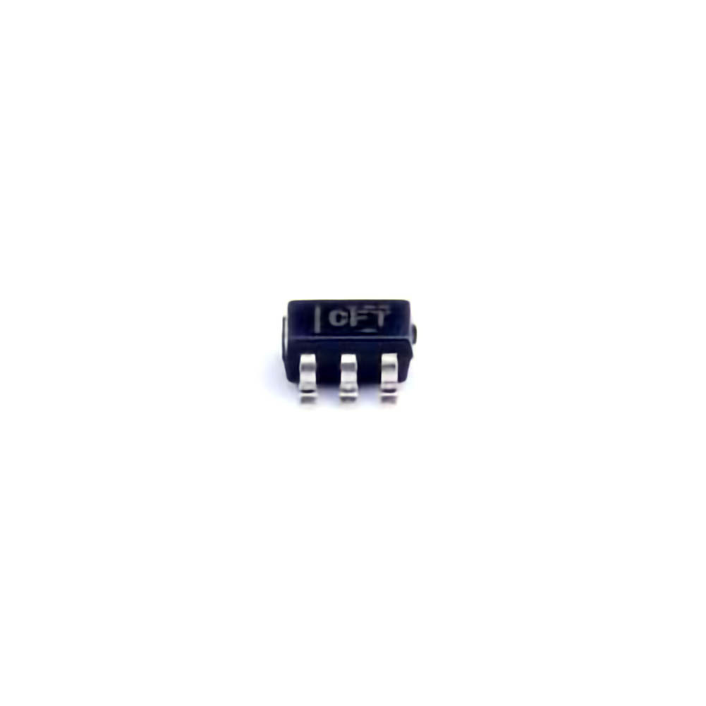
The MICROCHIP INA213AIDCKR is a precise current-sensing amplifier designed to help engineers monitor and measure current in various electrical systems. However, like any component, users may occasionally encounter issues related to its performance. This article provides a comprehensive guide to common troubleshooting techniques and solutions, helping users ensure reliable and accurate current measurements in their applications.
INA213AIDCKR, troubleshooting, current sensing, solutions, performance, electrical systems, common issues, precision amplifier, engineering, current measurement, troubleshooting guide.
Understanding the INA213AIDCKR and Common Issues
Introduction to the INA213AIDCKR
The INA213AIDCKR is an integrated precision current-sensing amplifier, commonly used in industrial, automotive, and consumer electronics applications. It allows engineers to measure current with high accuracy over a wide input voltage range. The device uses a shunt resistor to detect voltage differences created by current flow, amplifying the voltage for easy measurement by downstream electronics like microcontrollers or analog-to-digital converters (ADC). Despite its high accuracy and reliability, users may face certain issues that affect the device’s performance.
In this section, we will explore the most common problems engineers may face when working with the INA213AIDCKR and the possible solutions to resolve them.
1. Inaccurate Current Readings
Problem: One of the most frequent issues when working with current sensing amplifiers like the INA213AIDCKR is inaccurate current readings. This can occur if the device is not properly calibrated or if there is a problem with the external components (like resistors or connections) used in the system.
Possible Causes:
Incorrect Shunt Resistor Value: If the shunt resistor is not correctly chosen or calibrated, the INA213AIDCKR may provide inaccurate measurements. The shunt resistance needs to be selected based on the expected current range, as too low or too high resistance will lead to errors in the measurement.
Offset Voltage: INA213AIDCKR amplifiers have a specified input offset voltage, and if this offset is not properly compensated for in the design, it could result in measurement inaccuracies.
Measurement Range Exceeded: The INA213AIDCKR has specific voltage and current ranges. If these are exceeded, the device will saturate or return incorrect readings.
Solution:
Verify Resistor Specifications: Double-check the value of the shunt resistor, ensuring it is within the recommended range and tolerances specified in the datasheet.
Offset Correction: Use the device’s internal offset correction features or implement external compensation if needed. Accurate calibration of the device at Power -up can help minimize offset errors.
Monitor the Measurement Range: Ensure that the expected current is within the operational range of the INA213AIDCKR, as exceeding the limits will lead to erroneous outputs.
2. Power Supply Noise
Problem: Power supply noise is another common issue in precision electronics. Variations in the supply voltage can introduce errors in the current measurement, especially in sensitive systems like those using INA213AIDCKR.
Possible Causes:
Power Supply Instability: Noise or ripple in the power supply can interfere with the INA213AIDCKR’s internal circuits, affecting its accuracy.
Poor Grounding: Inadequate grounding can introduce voltage spikes or noise into the circuit, leading to inaccurate readings.
Incorrect Filtering: If the power supply input is not adequately filtered, noise may cause the device to behave erratically.
Solution:
Add Decoupling capacitor s: Use decoupling Capacitors at the power supply pins to minimize noise and ensure stable operation. Capacitors should be placed as close as possible to the pins for effective filtering.
Improve Grounding Practices: Make sure that all ground connections are solid and low-resistance. Avoid long ground traces and ensure that high-current paths are separated from sensitive signal paths.
Use Low Noise Power Supply: If possible, use a low-noise, stable power supply to reduce the risk of noise affecting the device’s performance.
3. Improper Voltage Reference
Problem: The INA213AIDCKR uses a reference voltage for output scaling, and using an improper reference can distort the readings. This problem typically occurs when the reference voltage is not stable or when the reference pin is left floating.
Possible Causes:
Floating Reference Pin: If the reference voltage pin (Vref) is not properly connected or left floating, the output readings may be erratic or unstable.
Incorrect Reference Voltage: Using a reference voltage that is too high or too low relative to the desired output range can lead to inaccurate or inconsistent measurements.
Solution:
Ensure Proper Connection to Vref Pin: Always connect the Vref pin to a stable reference voltage. This could be a dedicated low-dropout regulator (LDO) or a precision voltage reference.
Check for Stability: Make sure that the reference voltage is stable and within the range recommended in the datasheet to avoid any discrepancies in the output.
4. Incorrect Configuration of Gain Settings
Problem: The INA213AIDCKR allows users to configure the gain for the current sense measurement. If the gain is set incorrectly, the resulting current reading may be amplified or attenuated, leading to incorrect measurements.
Possible Causes:
Incorrect Gain Selection: The INA213AIDCKR offers multiple gain settings. If the wrong setting is selected based on the expected current range, it can lead to out-of-range measurements.
Incorrect External Components for Gain Setting: The external components used to set the gain (such as resistors in the gain configuration circuit) could be incorrectly selected or have drifted over time.
Solution:
Review Gain Configuration: Check the gain settings against the expected current range for the application. Use the datasheet formulas to ensure that the gain is appropriately selected.
Calibrate the System: If the system is not providing accurate readings, recalibrate the amplifier by adjusting the gain settings or recalculating the resistor values used in the gain network.
Advanced Troubleshooting Tips and Solutions for INA213AIDCKR
5. Overload Condition and Saturation
Problem: Another common issue with the INA213AIDCKR is overload or saturation, which happens when the measured current exceeds the device’s maximum input range. This leads to the device outputting the maximum value (saturation), preventing accurate measurement of higher currents.
Possible Causes:
Exceeding Maximum Current Limits: The INA213AIDCKR has a defined input current range. If the current exceeds this range, the device may saturate, and accurate measurements will no longer be possible.
Improper Shunt Resistor Size: A very low value for the shunt resistor could cause the voltage drop across it to be too small to measure accurately at higher currents, causing saturation.
Solution:
Monitor Current Levels: Always monitor the current levels to ensure they are within the operational limits of the INA213AIDCKR. If necessary, use a higher power-rated current shunt resistor.
Use a Range-Adjustable Shunt: For systems where current levels can vary widely, consider using a programmable or range-adjustable shunt to keep the voltage drop within an accurate measurable range.
6. Incorrect Output Behavior
Problem: In some cases, users may observe unexpected or erratic behavior in the output, such as oscillations or unexpected jumps in values.
Possible Causes:
External Interference: EMI (electromagnetic interference) from surrounding circuitry can couple into the signal lines, causing instability.
Inadequate Filtering of Output Signals: If the output signal is not properly filtered, high-frequency noise or spikes can cause erratic readings.
Poor PCB Layout: Issues with PCB layout, such as long signal traces or improper routing, can also lead to unpredictable behavior.
Solution:
Use Proper Shielding: Add shielding around sensitive signal paths to reduce the risk of external interference. This is especially important in noisy industrial environments.
Implement Output Filtering: Add low-pass filters to the output to smooth out any high-frequency noise. Use proper capacitor values to effectively filter out unwanted frequencies.
Optimize PCB Layout: Ensure that signal paths are kept short and that there is adequate separation between high-current and low-voltage paths to minimize noise coupling.
7. Thermal Management
Problem: Like most electronic components, the INA213AIDCKR is sensitive to temperature fluctuations. High temperatures can cause drift in performance or even permanent damage to the device.
Possible Causes:
High Operating Temperatures: The INA213AIDCKR has a specified operating temperature range. Exceeding this range can lead to performance degradation.
Thermal Runaway: If the device is dissipating too much power or is exposed to excessive heat, it could enter a state known as thermal runaway, where increasing temperature leads to further increases in current draw.
Solution:
Ensure Adequate Cooling: Use heat sinks or fans to cool the system, especially in high-power applications.
Monitor Temperature: Implement temperature sensors to monitor the operating temperature of the INA213AIDCKR and take corrective action if the temperature exceeds safe limits.
Conclusion
The INA213AIDCKR is an excellent precision current-sensing amplifier, but like any electronic device, it can experience performance issues if not properly designed, calibrated, or maintained. By understanding the common problems and implementing the solutions outlined in this article, engineers can ensure that their current-sensing systems remain accurate, reliable, and efficient.
Whether it’s checking the resistor values, improving power supply noise rejection, adjusting the gain settings, or ensuring proper temperature control, each step will contribute to achieving precise and consistent current measurements in your applications.
If you’re looking for models of commonly used electronic components or more information about INA213AIDCKR datasheets, compile all your procurement and CAD information in one place.
( Partnering with an electronic component supplier) sets your team up for success, ensuring that the design, production and procurement processes are streamlined and error-free. (Contact us) for free today.

