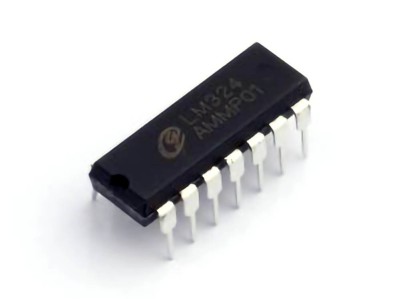
This article explores the application of the CD4017 Decade Counter IC in the design of a digital frequency meter. The CD4017 is a versatile and easy-to-use component that can be used for counting pulses and converting these pulses into readable digital data. We will delve into how it can be used in frequency measurement applications, its benefits, and provide a step-by-step guide on building a simple yet effective digital frequency meter.
CD4017, digital frequency meter, frequency counter, circuit design, application, pulse counting, electronics, decade counter, frequency measurement.
Introduction to CD4017 and Its Role in Digital Frequency Measurement
Frequency measurement is a crucial aspect in various fields of electronics, from Audio testing to signal processing and telecommunications. To measure the frequency of an incoming signal, it is essential to convert the signal's frequency into a readable value, which can be achieved using a digital frequency meter. One of the most popular ICs used for this task is the CD4017 Decade Counter.
What is the CD4017 Decade Counter?
The CD4017 is a CMOS (Complementary Metal-Oxide-Semiconductor) integrated circuit, designed to count digital pulses and divide the frequency of a Clock signal. It is often referred to as a "decade counter" because it can count up to ten clock pulses (from 0 to 9), and then it resets. This counting function makes it an ideal component for frequency measurement, as each pulse that enters the IC can represent a unit of time. When combined with a suitable display and other components, the CD4017 can convert pulses into a readable frequency value.
How the CD4017 Works
The CD4017 has a total of 10 output pins, each of which is activated sequentially with every incoming clock pulse. These outputs can be used to trigger other components in the circuit, such as a seven-segment display or a microcontroller, to show the frequency in a human-readable format.
The IC operates by receiving a clock signal, which is typically a periodic waveform that represents the frequency to be measured. For each pulse in the clock signal, the CD4017 increments its output count. When it reaches the 10th pulse, it resets to 0, allowing it to continuously count over time. This characteristic makes it pe RF ect for use in applications where the frequency of a signal needs to be measured over extended periods.
Benefits of Using the CD4017 in Frequency Meters
The CD4017 provides several benefits when used in frequency meter designs:
Simplicity: The IC is relatively simple to use, requiring only a clock signal and a few additional components to operate.
Low Power Consumption: As a CMOS device, the CD4017 operates with low power, making it suitable for battery-powered devices.
Wide Frequency Range: The CD4017 can handle a wide range of frequencies, depending on the clock signal and the circuit design.
Cost-Effective: The IC is inexpensive and widely available, making it an attractive option for hobbyists and professionals alike.
By counting the pulses of a clock signal, the CD4017 can be incorporated into a circuit to measure the frequency of an unknown signal and convert it into a digital display. Let's explore how this can be achieved with a practical circuit design.
Circuit Design and Practical Application of the CD4017 in a Digital Frequency Meter
Now that we have a basic understanding of the CD4017 and its functionality, let’s take a look at how to build a simple digital frequency meter using this IC. We will discuss the key components, step-by-step circuit design, and how to implement the frequency counter.
Components Required for the Frequency Meter
To design a frequency meter with the CD4017, the following components are required:
CD4017 Decade Counter IC: This is the heart of the frequency meter, responsible for counting the incoming clock pulses.
555 Timer IC: A commonly used timer that will generate a stable clock signal for the CD4017. This signal determines the time interval for counting.
Seven-Segment Display: This will display the counted values, which represent the frequency.
Resistors and Capacitors : These components will be used for timing and filtering purposes.
Power Supply: Typically, a 5V DC supply is adequate for powering the CD4017 and other components.
Basic Circuit Design
Let’s begin by designing a basic circuit to measure the frequency of an unknown signal using the CD4017.
Clock Generation:
The 555 timer IC is configured in astable mode to generate a square wave clock signal. This clock signal will be fed into the CD4017, which will count the pulses. The frequency of the 555 timer should be set according to the desired resolution of the frequency meter.
In this case, the frequency of the 555 timer is set to produce a pulse every 1 millisecond. This gives the CD4017 enough time to count each pulse without overflowing too quickly.
Pulse Counting:
The clock signal generated by the 555 timer is fed into the CD4017's clock input pin (pin 14). As each pulse arrives, the CD4017 increments its internal counter. Each output pin (Q0 to Q9) represents a decimal digit in the frequency reading.
For example, after 10 pulses, the CD4017 will output a high signal on pin Q0, then move to Q1 after 20 pulses, and so on. The counting continues indefinitely, resetting back to zero after every 10 pulses.
Displaying the Counted Value:
The outputs of the CD4017 are connected to a seven-segment display to show the counted value. The CD4017 provides a 1:10 counting ratio, which can be used to convert the number of clock pulses into a frequency value.
A simple 7-segment decoder circuit is used to convert the output from the CD4017 to drive the display. The display will show the count, which can then be interpreted as the frequency.
Scaling the Frequency:
To scale the measured frequency, additional circuitry may be required to adjust the time base. For example, a prescaler or frequency divider can be used to divide the input signal into a lower frequency range that can be accurately counted by the CD4017.
In a more advanced setup, a microcontroller could be used to perform more complex calculations or to display the frequency in standard units (Hz) rather than just the raw count of pulses.
Calibration:
Once the circuit is set up, it can be calibrated by feeding it a known frequency signal and adjusting the clock generation circuit until the displayed value matches the known frequency. This ensures that the frequency meter provides accurate readings across the desired range of frequencies.
Applications of the CD4017-Based Frequency Meter
This simple frequency meter design using the CD4017 IC can be used in various applications, including:
Testing Oscillators and Signal Generators: It provides a simple method for testing the output frequency of oscillators and signal generators in electronics projects.
Audio Frequency Measurement: The meter can measure audio frequencies, making it useful for audio engineers and hobbyists working with audio equipment.
Signal Analysis: The frequency meter can be used to analyze the frequency of various signals in telecommunications and RF ( radio frequency ) applications.
Educational Tools: The simplicity of the CD4017 circuit makes it an excellent teaching tool for students learning about frequency measurement and digital counters.
Conclusion
The CD4017 Decade Counter IC offers an easy and cost-effective solution for building a digital frequency meter. With its ability to count pulses and display the results on a seven-segment display, this IC is a powerful tool for anyone needing to measure and analyze frequencies in electronic circuits. By carefully designing the circuit, selecting the appropriate components, and calibrating the system, a precise and reliable frequency meter can be built with minimal effort and expense.
In the next steps, enthusiasts and professionals alike can expand on this design, integrating more advanced features such as higher-resolution displays, microcontroller interface s, and frequency scaling for more precise and versatile applications. Whether for testing, analysis, or educational purposes, the CD4017 provides a solid foundation for frequency measurement circuits.
Partnering with an electronic components supplier sets your team up for success, ensuring the design, production, and procurement processes are quality and error-free.


