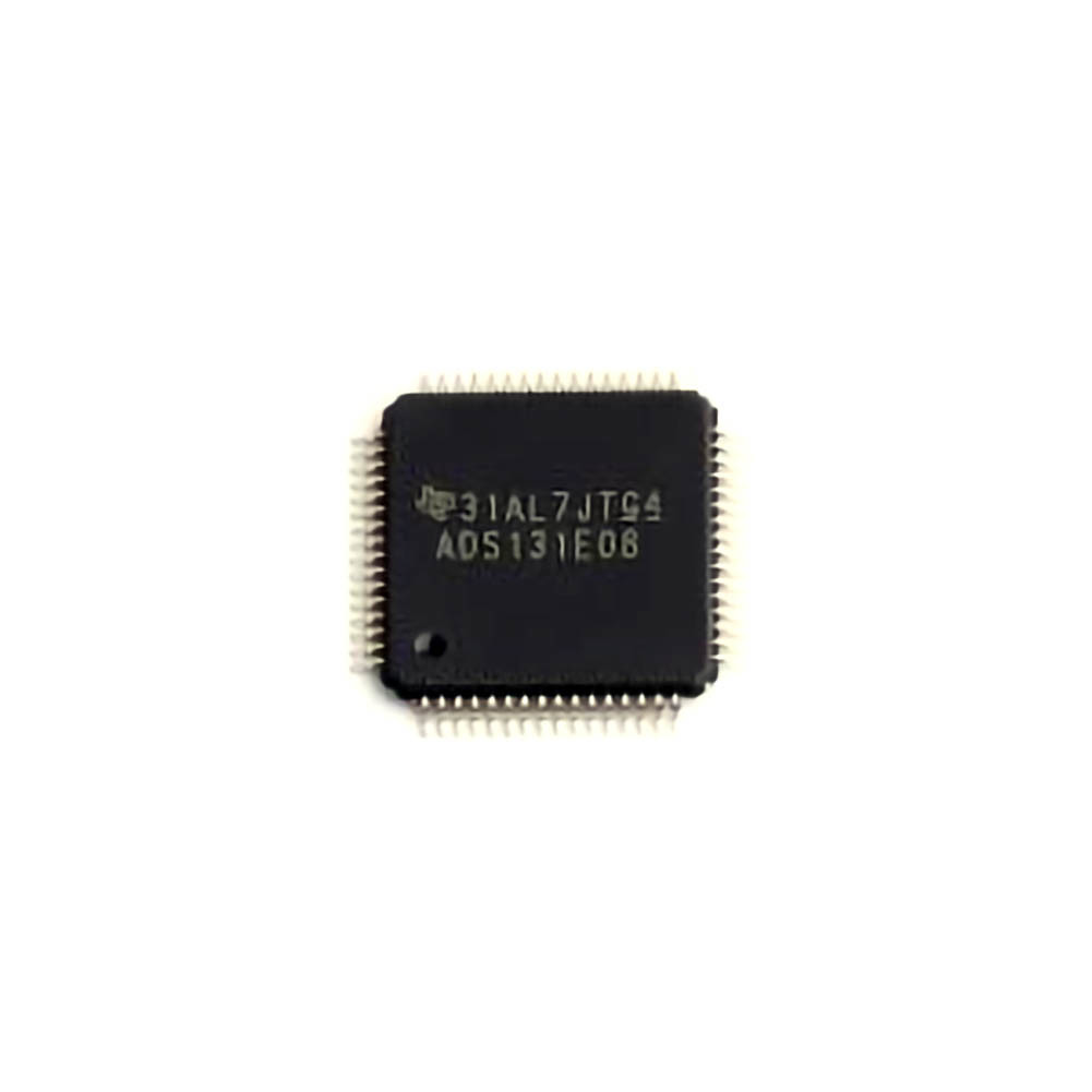
The Texas Instruments ADS131E08IPAGR is a high-precision analog-to-digital converter (ADC) used in various industrial, medical, and consumer electronics applications. This article provides a comprehensive troubleshooting guide, covering common issues and solutions to help engineers and developers optimize their designs for stability and performance.
ADS131E08IPAGR, troubleshooting, solutions, ADC, analog-to-digital converter, electrical issues, signal processing, performance optimization
Common Troubleshooting Scenarios with the ADS131E08IPAGR
The ADS131E08IPAGR is a robust and Power ful 8-channel, 24-bit delta-sigma ADC that provides high precision and low noise for various applications, such as industrial control systems, medical equipment, and precision instrumentation. However, like any complex piece of technology, it can experience issues that may affect its performance. Identifying these issues and finding the appropriate solutions can significantly enhance system reliability.
In this section, we will cover common troubleshooting scenarios encountered with the ADS131E08IPAGR and provide practical solutions to resolve them.
1. No Output Data or Unstable Data
One of the most common issues users face with the ADS131E08IPAGR is no output data or unstable data. This can be caused by a number of factors, including poor power supply conditions, incorrect configuration settings, or Timing issues.
Possible Causes:
Power Supply Issues: The ADS131E08IPAGR requires a clean and stable power supply, typically operating at 3.3V or 5V. Power supply noise, fluctuations, or incorrect voltage levels can lead to erratic behavior or a complete lack of output.
Improper Configuration: Incorrect register settings or configuration values might prevent the ADC from properly converting signals or sending data to the host microcontroller.
Timing Mismatch: The ADS131E08IPAGR interface s with external components through a serial interface (SPI). If the Clock signals are not synchronized properly, the ADC may not output data as expected.
Solution:
Check Power Supply: Ensure that the power supply voltage is within the specified range and that there is no significant noise or ripple in the supply voltage. Use an oscilloscope to verify voltage stability.
Review Configuration Registers: Recheck the configuration registers of the ADS131E08IPAGR. Specifically, verify the settings for the data rate, reference voltage, and sampling rate. Make sure that the device is correctly set to operate in the desired mode (e.g., continuous conversion mode, single-shot mode).
Verify SPI Timing: Use an oscilloscope to ensure that the SPI clock (SCLK) is synchronized with the data clock (DRDY) signal. Check that the correct data bits are being transmitted and that the communication protocol is being followed.
2. Inaccurate or Noisy Output
Another common issue with high-precision ADCs like the ADS131E08IPAGR is output data that is inaccurate or excessively noisy. This is particularly noticeable in applications that require precise measurements, such as medical diagnostics or industrial automation.
Possible Causes:
Grounding Issues: Poor grounding or a noisy ground plane can introduce unwanted noise into the measurement process, resulting in inaccuracies.
Reference Voltage Instability: The ADS131E08IPAGR uses an internal reference voltage to measure the input signal. If the reference voltage is unstable or noisy, it can cause inaccurate conversions.
External Interference: External electromagnetic interference ( EMI ) or crosstalk between channels can also introduce noise into the ADC readings.
Input Signal Noise: If the analog input signal is noisy or improperly filtered, the ADC can misinterpret the signal, leading to erroneous output.
Solution:
Improve Grounding: Ensure that the ground plane is solid and continuous. Use star grounding techniques, and minimize the length of ground traces. Also, consider using ferrite beads or low-pass filters to reduce high-frequency noise.
Stabilize Reference Voltage: Use external reference sources with better noise performance if required, or add decoupling Capacitors close to the reference input pins to stabilize the reference voltage.
Shielding and Layout Improvements: Implement shielding around sensitive analog signals to protect them from external EMI. Additionally, route high-speed digital signals away from sensitive analog traces.
Signal Conditioning: Add proper analog filtering at the input to remove high-frequency noise. Low-pass filters can help clean up the signal before it reaches the ADC. Consider using differential input signals if possible, as they tend to be less susceptible to noise.
3. Overloading or Saturation of the Input Channels
The ADS131E08IPAGR has a wide input voltage range, but if the input signal exceeds the device’s input range, the channels can become overloaded or saturated, leading to distorted readings.
Possible Causes:
Excessive Input Voltage: Input signals that exceed the reference voltage or supply voltage can cause clipping or saturation of the ADC.
Incorrect Gain Settings: The gain settings may be too high for the input signal, resulting in saturation even if the signal itself is within the allowable range.
Solution:
Check Input Signal Levels: Ensure that the input signal is within the allowed input voltage range of the ADC. Use a voltage divider or buffer if necessary to scale the input signal to fit within the ADC’s input range.
Adjust Gain Settings: Review and adjust the gain settings in the ADS131E08IPAGR configuration. If the gain is too high for the input signal, consider reducing it to prevent saturation. Use the internal gain options to match the signal level to the ADC’s input range.
4. Unexpected Data Behavior During Power-Up
Sometimes, the ADS131E08IPAGR may exhibit unexpected data behavior during power-up. This could include random values, incorrect initialization, or failure to begin conversion.
Possible Causes:
Power Sequencing Issues: If the power supply rails are not applied in the correct sequence, or if the supply voltage ramps up too quickly, the ADC may not initialize correctly.
Reset Pin Issues: The RESET pin may not be properly asserted at power-up, leading to improper initialization of the internal circuits.
Decoupling capacitor Problems: Insufficient or incorrectly placed decoupling capacitors can cause the ADC to behave unpredictably during startup.
Solution:
Check Power-Up Sequencing: Ensure that all power supply rails are ramped up within the specifications outlined in the datasheet. Ensure the VDD pin is powered first, followed by the analog supply pins (if applicable).
Use the RESET Pin Properly: Make sure the RESET pin is held low for a sufficient period during power-up to ensure proper initialization. If necessary, use an external reset circuit to guarantee the correct reset sequence.
Review Decoupling Capacitors: Ensure that decoupling capacitors are placed as close to the power pins as possible. Typically, 0.1µF ceramic capacitors should be used to filter out high-frequency noise.
Advanced Troubleshooting and Optimization for ADS131E08IPAGR
While the solutions outlined in Part 1 cover common issues, there are more advanced troubleshooting strategies that can help optimize the performance of the ADS131E08IPAGR in demanding applications.
1. Improving System Clock Synchronization
The performance of the ADS131E08IPAGR can be significantly affected by clock jitter or skew. In systems where multiple ADCs are being used, clock synchronization is critical for accurate data collection.
Possible Causes:
Clock Skew Between Devices: If multiple ADS131E08IPAGR devices are used in a system, clock skew between devices can lead to misaligned data, which can result in inaccurate measurements or data corruption.
Poor Clock Source Stability: A poor clock source can introduce jitter, which affects the ADC’s timing and conversion accuracy.
Solution:
Use a Low-Jitter Clock Source: Employ a low-jitter clock oscillator to drive the ADS131E08IPAGR. This will reduce clock noise and ensure accurate sampling and conversion.
Careful PCB Layout for Clock Distribution: Pay close attention to the layout of the clock traces on the PCB. Minimize trace lengths and use proper termination techniques to avoid signal degradation or reflections.
Implement Clock Buffers or Drivers : In systems with multiple ADCs, use clock buffers or drivers to distribute the clock signal evenly and reduce the impact of skew.
2. Advanced Filtering Techniques
Advanced filtering techniques are essential when working with high-precision ADCs like the ADS131E08IPAGR, especially when dealing with noisy environments or weak signals.
Possible Causes:
Inadequate Filtering: Without proper filtering, the ADC may pick up noise from the power supply, external sources, or the input signal.
Incorrect Filter Design: The choice of filter type and cut-off frequency is critical in preventing aliasing and noise.
Solution:
Use Anti-Aliasing Filters: Place anti-aliasing filters in front of the ADC inputs to remove high-frequency components that could cause aliasing in the digital output. A low-pass filter with a cut-off frequency just below the Nyquist rate is ideal.
Design Custom Filters: If required, design custom filters using op-amps and resistors to filter specific frequency ranges. Consider active filters for better performance and precision.
3. Thermal Management and Environmental Factors
Temperature fluctuations can impact the performance of high-precision ADCs. The ADS131E08IPAGR is sensitive to temperature changes, and improper thermal management can lead to drift in measurements.
Possible Causes:
Thermal Drift: Temperature changes can affect the internal reference voltage, as well as the input signals, leading to inaccurate data.
Overheating: Excessive heat can cause the ADC to malfunction or even permanently damage it.
Solution:
Implement Thermal Compensation: Use temperature sensors in critical locations of your system to monitor the operating temperature. If thermal drift is significant, consider implementing temperature compensation algorithms to adjust the output.
Improve Cooling: Use heat sinks, passive cooling methods, or fans to maintain a stable temperature range for the ADS131E08IPAGR. Ensure adequate airflow in the system enclosure to prevent overheating.
4. Optimizing Resolution and Accuracy
The ADS131E08IPAGR offers high resolution (up to 24 bits), but achieving the full resolution requires careful system design and optimization.
Possible Causes:
Gain and Reference Mismatch: Incorrect gain settings or an unstable reference can reduce the effective resolution of the ADC.
Noise or Interference: Noise from the power supply or input signal can degrade the accuracy of the ADC, preventing it from achieving its theoretical resolution.
Solution:
Use High-Quality Reference Voltages: Ensure that the reference voltage is stable and accurate. Consider using external precision reference devices for optimal performance.
Optimize Signal Conditioning: Add precision signal conditioning components like low-noise amplifiers (LNAs) and filters to ensure that the input signal is within the ideal range for conversion.
5. Leveraging the Internal Features for Performance Boost
The ADS131E08IPAGR has several internal features, such as built-in filters, programmable gain amplifiers (PGAs), and a differential input mode, that can enhance system performance when used correctly.
Solution:
Use Built-In PGAs: The internal programmable gain amplifiers can be used to boost weak input signals before conversion. Adjusting the gain can help optimize the signal-to-noise ratio and increase measurement accuracy.
Enable Internal Filters: Utilize the built-in digital filters to reduce the noise and improve the overall quality of the digital output.
By carefully following these troubleshooting steps and optimization techniques, engineers can maximize the performance of the ADS131E08IPAGR ADC in their designs. Whether dealing with power supply issues, timing mismatches, or signal noise, a systematic approach to troubleshooting can ensure stable, accurate, and reliable operation in any application.
If you’re looking for models of commonly used electronic components or more information about ADS131E08IPAGR datasheets, compile all your procurement and CAD information in one place.
(Partnering with an electronic component supplier) sets your team up for success, ensuring that the design, production and procurement processes are streamlined and error-free. (Contact us) for free today

