Understanding the ADG719BRTZ and Common Issues
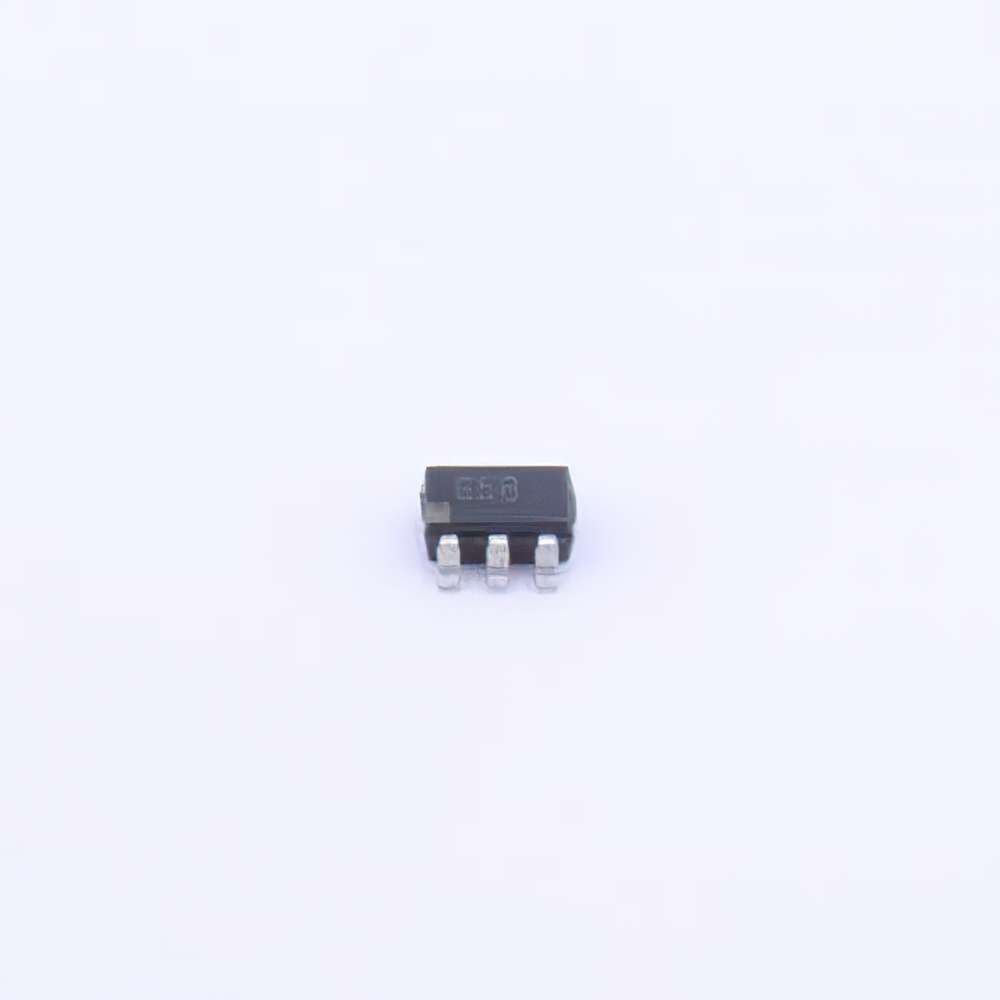
The ADI ADG719BRTZ is a high-performance, low-on- Resistance analog switch that has found widespread use in a range of applications, from industrial systems and medical instrumentation to communication devices. Known for its reliability and precision, the ADG719BRTZ has established itself as a top choice for engineers who require seamless signal routing. However, as with any sophisticated electronic component, users can encounter specific challenges that may compromise its performance. This article will delve into the most common troubleshooting issues associated with the ADG719BRTZ and provide practical solutions to maintain optimal operation.
1. Signal Distortion and Loss
One of the most common issues when using the ADG719BRTZ is signal distortion or loss, which can occur if the component is not properly integrated into the circuit. This issue can manifest as unexpected attenuation or unexpected behavior in the signal path.
Solution:
To troubleshoot this issue, first check the connection integrity of the analog signal paths. Ensure that the solder joints are solid and that there are no broken or weak connections that could lead to resistance variations. Additionally, verify that the board layout meets the recommended specifications, especially in terms of trace width and grounding, to minimize noise interference. Proper grounding reduces the chances of signal loss and distortion, and it also enhances the overall performance of the ADG719BRTZ.
2. Incorrect Logic Control Signals
The ADG719BRTZ operates using logic control signals that dictate its switching behavior. One of the main issues users face is that the logic control levels are either not properly configured or are inconsistent with the component’s specifications, leading to unreliable operation.
Solution:
Always confirm that the control signals are within the voltage range specified in the datasheet. The control input should be compatible with the logic levels of the circuit it is integrated into. Pay special attention to the logic “high” and “low” voltage thresholds and ensure that they are within the specified limits to avoid erratic switching behavior. Using a voltage level translator can be a useful way to match logic levels if there is a discrepancy between the control circuit and the ADG719BRTZ.
3. High On-Resistance (RON) Issues
High on-resistance (RON) can lead to signal attenuation and degradation in circuit performance, which is particularly detrimental in precision applications.
Solution:
To address high on-resistance issues, ensure that the Power supply voltage is within the recommended range. Operating outside of the recommended voltage range can increase RON and compromise performance. Also, check that the environmental conditions, such as temperature, are within the optimal range for operation, as RON can increase with temperature variations. Using proper thermal management solutions, such as heat sinks or improved PCB designs for heat dissipation, can mitigate this issue.
4. Power Supply Considerations
Many users may encounter unexpected behavior due to power supply issues. The ADG719BRTZ requires a stable and well-regulated supply to function correctly. Variations in the power supply voltage or improper decoupling can lead to malfunction.
Solution:
Make sure that the power supply is stable and free from fluctuations. Using decoupling capacitor s near the power supply pins of the component can help filter out high-frequency noise. Typically, a combination of a 0.1µF ceramic capacitor and a 10µF electrolytic capacitor is recommended. Proper decoupling ensures that the ADG719BRTZ receives a steady power supply, improving performance and preventing unintended behavior.
5. Temperature and Environmental Impact
The performance of the ADG719BRTZ can be influenced by temperature and environmental factors. For applications that require operation in harsh environments, this can become a critical concern.
Solution:
Ensure that the component is used within the operating temperature range specified in its datasheet. For high-temperature applications, using a heatsink or designing the PCB with thermal vias can help dissipate heat efficiently. Additionally, proper enclosure with heat management capabilities can protect the circuit and the ADG719BRTZ from extreme environmental conditions.
Advanced Troubleshooting Tips and Best Practices
While the issues mentioned above cover many common problems, there are additional, more nuanced troubleshooting techniques and best practices that can help engineers optimize the performance of the ADG719BRTZ and ensure long-term reliability.
6. Proper PCB Design and Layout
The design and layout of the printed circuit board (PCB) play a crucial role in the overall performance of the ADG719BRTZ. Poor PCB design can result in signal integrity issues, increased noise, and even damage to the component.
Solution:
To prevent such issues, follow best practices for PCB design. Ensure that analog signal traces are kept as short as possible to minimize inductance and potential signal loss. Proper shielding and routing techniques can protect the analog signals from noise sources. Additionally, maintaining a good ground plane that is continuous and free of interruptions can greatly enhance the grounding and, consequently, the component’s performance. Finally, avoid placing high-speed digital circuits and analog circuits too close to each other on the same PCB, as this can lead to crosstalk.
7. ESD (Electrostatic Discharge) Protection
Electrostatic discharge (ESD) can pose a serious risk to the ADG719BRTZ, potentially causing immediate or gradual damage to the component.
Solution:
To safeguard against ESD, incorporate ESD protection devices such as TVS (Transient Voltage Suppression) diodes in your circuit design. Placing these diodes near the input/output pins of the ADG719BRTZ can help shunt high-voltage transients to the ground and protect the component. It’s also essential to handle the component using proper ESD protection measures during assembly and maintenance.
8. Overvoltage and Reverse Polarity
Applying an overvoltage or incorrect polarity to the ADG719BRTZ can result in permanent damage to the component and lead to circuit failure.
Solution:
To avoid these risks, double-check the power and signal connections before powering up the circuit. Use protective diodes or a series resistor to limit current and prevent damage due to potential overvoltage scenarios. A voltage regulator can be used to ensure that the supply voltage remains within safe operating limits.
9. Inadequate Testing and Debugging Techniques
Finally, engineers may encounter challenges if they fail to properly test and debug their circuit configurations. Inadequate testing can lead to undetected issues that compromise the circuit’s overall functionality.
Solution:
Implement a thorough testing strategy using an oscilloscope to monitor the analog signals and verify proper switching behavior. Additionally, use a multimeter to check for continuity and ensure that the connections are as intended. Employing automated test equipment (ATE) for larger production runs can identify faults more efficiently and prevent potential issues.
10. Ensuring Proper Component Selection
In some cases, issues with the ADG719BRTZ may arise not from the component itself, but from the surrounding components that interact with it. Ensuring that all connected components are compatible and of high quality can greatly reduce the risk of circuit issues.
Solution:
Verify that the component values, such as resistors and capacitors, meet the design requirements specified in the circuit design. Also, choose components with tight tolerance levels when precision is critical.
By following these troubleshooting tips and solutions, engineers can maximize the performance and reliability of the ADG719BRTZ in their applications. Taking the time to address common issues proactively can lead to a significant improvement in circuit design and functionality.
If you’re looking for models of commonly used electronic components or more information about ADG719BRTZ datasheets, compile all your procurement and CAD information in one place.
(Partnering with an electronic component supplier) sets your team up for success, ensuring that the design, production and procurement processes are streamlined and error-free. (Contact us) for free today


