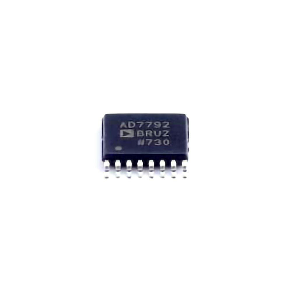
Introduction to AD7792BRUZ and Common Troubleshooting Issues
The ADI AD7792BRUZ is a high-precision, low- Power , 24-bit analog-to-digital converter (ADC) designed by Analog Devices. It is ideal for applications that require high accuracy and low power consumption, such as measurement systems, Instrumentation , and process control. Despite its reliable design, users often face various issues when working with this sophisticated ADC, especially in complex industrial setups.
Understanding these challenges and knowing how to troubleshoot the AD7792BRUZ can make a significant difference in achieving optimal performance. This article will address the most common issues encountered during the usage of this device and propose practical solutions.
1. Power Supply Issues
Power supply problems are one of the most common causes of malfunction in precision ADCs like the AD7792BRUZ. A stable, clean, and adequately regulated power supply is essential for ensuring the accurate conversion of analog signals into digital data. The AD7792BRUZ operates at a supply voltage of 2.7V to 5.25V, and any deviation from this range can lead to erratic behavior, reduced accuracy, or total failure.
Symptoms:
The ADC fails to power up.
The output is unstable or fluctuates.
The conversion results are erroneous or incorrect.
Solutions:
Check the Voltage Level: Ensure the power supply voltage is within the specified range (2.7V to 5.25V). Use a precision multimeter to measure the supply voltage and verify it is stable.
Power Supply Decoupling: Add decoupling capacitor s near the AD7792BRUZ power supply pins (VDD and GND) to filter out high-frequency noise. A typical recommendation is a 0.1µF ceramic capacitor in parallel with a larger 10µF electrolytic capacitor.
Grounding: Improper grounding can lead to voltage spikes and noise, which interfere with the ADC’s operation. Ensure that the ground connections are solid and low-resistance.
Use a Low-Noise Power Source: To minimize ripple, use a low-noise voltage regulator or a dedicated power supply with excellent noise rejection for the AD7792BRUZ.
2. Incorrect Reference Voltage
The AD7792BRUZ relies on a precise reference voltage (REF) for accurate conversion. If the reference voltage is unstable, incorrect, or poorly regulated, the ADC output will be inaccurate, leading to measurement errors.
Symptoms:
The digital output is inconsistent or fluctuates.
The ADC output seems to be offset or scaled incorrectly.
Solutions:
Check the Reference Voltage: The reference voltage (REF) must be within the specified range of 2.4V to VDD for accurate conversions. Measure the reference voltage using a precision multimeter or oscilloscope.
Use a Stable, Low Noise Reference Source: A poor-quality reference voltage source can introduce errors into the ADC’s conversion process. Use a low-noise, stable reference voltage source, such as an external precision reference IC.
Decouple the Reference Pin: Just like the power supply, the reference pin should be decoupled with Capacitors (0.1µF ceramic and 10µF electrolytic) to minimize noise.
Check for External Interference: Ensure that the reference voltage is not affected by external noise sources or electromagnetic interference ( EMI ). Shield the reference voltage line if necessary.
3. Incorrect Configuration of the ADC
The AD7792BRUZ has various configuration settings that determine the ADC’s behavior, including the input channel selection, gain, and data rate. Incorrect configuration can lead to inaccurate or missing data.
Symptoms:
The ADC outputs constant values (e.g., 0x000000 or 0xFFFFFF).
The ADC does not respond to input signals.
The data appears skewed or incorrect.
Solutions:
Review Configuration Registers: The AD7792BRUZ uses several control registers that configure input channels, gain, and the operation mode. Make sure that the configuration matches your application’s requirements.
Check Input Channel Selection: If you’re using differential inputs, ensure the correct input channels are selected via the control register. Similarly, verify the single-ended input mode if applicable.
Set the Correct Gain: The AD7792BRUZ allows setting various gain values (1, 2, 4, 8, 16, etc.). Ensure that the gain setting matches the expected input signal range to avoid saturation or clipping of the input signal.
Data Rate Settings: Verify that the data rate is appropriate for the application. The AD7792BRUZ offers different data rates, and choosing an incorrect one may lead to inaccurate readings or slower conversions.
Reset the ADC: If unsure about the configuration settings, perform a full reset to return the ADC to its default settings and reconfigure as needed.
4. Noise and Interference
Noise and electromagnetic interference (EMI) can significantly affect the performance of the AD7792BRUZ. Since the ADC operates at very high precision, even small amounts of noise can result in significant measurement errors.
Symptoms:
Erratic or noisy output.
Fluctuations in the digital output even with a stable input signal.
Incorrect conversion values despite correct configuration.
Solutions:
Minimize EMI: Use shielding or ground planes to reduce external noise and electromagnetic interference. Proper PCB layout practices, such as keeping analog and digital traces separate, can also minimize noise coupling.
Use Proper Filtering: Low-pass filters on the input signal can help reduce high-frequency noise. Capacitors and Resistors should be chosen to filter out unwanted frequencies while preserving the signal bandwidth of interest.
Twisted Pair Cables: If you’re using long wires for signal transmission, consider using twisted pair cables to reduce the effects of external noise. Twisting the wires together helps cancel out induced noise.
PCB Layout Considerations: On the PCB, minimize the length of analog signal traces, and keep them as short as possible. This will help reduce the susceptibility to noise. Use ground planes to provide a low impedance path for signals and minimize noise.
Advanced Troubleshooting Solutions and Best Practices for AD7792BRUZ
Now that we’ve covered the fundamental troubleshooting solutions for the AD7792BRUZ, let’s explore some more advanced strategies and best practices to ensure the optimal operation of this ADC in demanding environments.
1. Temperature Sensitivity and Stability
Temperature variations can significantly affect the performance of precision ADCs. The AD7792BRUZ is designed to function within a temperature range of -40°C to 85°C, but significant deviations from this range can lead to drift in the output readings.
Symptoms:
The output drift changes with temperature.
Measurement inaccuracies become more pronounced when the device is exposed to temperature fluctuations.
Solutions:
Calibrate Over Temperature: If you expect the AD7792BRUZ to operate in environments with large temperature variations, consider implementing a calibration routine that accounts for temperature changes. Some designs include temperature sensors that can be used to compensate for temperature-induced drift.
Use a Temperature-Compensated Reference: One way to mitigate the impact of temperature on the ADC’s accuracy is by using a temperature-compensated reference voltage source, which remains stable across a broad temperature range.
Thermal Management : If you are using the AD7792BRUZ in a high-heat environment, consider improving thermal dissipation. Use heat sinks, ensure adequate ventilation, or add temperature sensors to monitor the device’s thermal performance.
2. Interfacing with Microcontrollers
The AD7792BRUZ typically interface s with a microcontroller or FPGA via a serial interface (SPI). Mis Communication between the ADC and the microcontroller can cause data corruption or incorrect readings.
Symptoms:
No data received from the ADC.
The data received is corrupted or incorrect.
The microcontroller cannot communicate with the AD7792BRUZ.
Solutions:
Check SPI Communication: Ensure that the SPI communication parameters (clock polarity, clock phase, bit order, etc.) are correctly configured on both the AD7792BRUZ and the microcontroller. Verify that the data is correctly shifted out of the ADC and into the microcontroller.
Verify Chip Select (CS) Line: The chip select (CS) line must be pulled low to initiate communication with the ADC. Check that the CS pin is being correctly toggled by the microcontroller.
Use Pull-Up/Pull-Down Resistors: If necessary, use pull-up or pull-down resistors on the SPI lines to ensure proper logic levels and communication integrity.
Timing Constraints: Ensure that the timing of the SPI transactions (clock speed, setup time, hold time, etc.) is within the ADC’s operating specifications. Violating these timings can lead to data corruption.
3. Common-Mode Voltage and Input Protection
In differential input configurations, common-mode voltage and input protection are critical factors in ensuring accurate and reliable readings. Exceeding the common-mode voltage limits can damage the ADC or lead to erroneous readings.
Symptoms:
Differential input readings are incorrect.
The ADC becomes unresponsive or outputs incorrect data.
Solutions:
Ensure Common-Mode Voltage Is Within Limits: The AD7792BRUZ has specific common-mode voltage limits for differential inputs. Ensure that the input signals are within the allowed range relative to the reference voltage.
Input Overvoltage Protection: To protect the ADC from overvoltage conditions, use clamping diodes or resistors on the input pins to limit the input voltage to safe levels.
Use Instrumentation Amplifiers : If your signal source has a high common-mode voltage, consider using an instrumentation amplifier to ensure the differential voltage is within the ADC’s input range.
4. Final Verification and System Testing
Once the AD7792BRUZ is correctly configured and integrated into your system, it’s essential to perform comprehensive verification and testing to ensure its reliability and accuracy in real-world conditions.
Symptoms:
The system operates intermittently or unpredictably.
Data validation shows significant deviations from expected results.
Solutions:
Use Known Input Signals: During system testing, use precise, known input signals (e.g., a calibrated signal generator) to verify that the ADC is outputting correct and stable digital data.
Cross-check with External Instruments: If possible, cross-check the ADC output with an external instrument such as a high-precision DMM (digital multimeter) or oscilloscope to ensure measurement accuracy.
Conduct Long-Term Stability Tests: Run the system over an extended period to check for long-term stability and drift. This will help identify any temperature-related issues or power fluctuations that affect the ADC’s performance.
Conclusion
While the AD7792BRUZ is an incredibly powerful and accurate ADC, it does require careful attention to power supply integrity, reference voltage stability, proper configuration, and protection from noise and interference. By following the troubleshooting steps and best practices outlined in this guide, you can ensure that your AD7792BRUZ-based system operates with maximum accuracy and reliability, even in demanding industrial applications.
If you’re looking for models of commonly used electronic components or more information about AD7792BRUZ datasheets, compile all your procurement and CAD information in one place.
( Partnering with an electronic component supplier) sets your team up for success, ensuring that the design, production and procurement processes are streamlined and error-free. (Contact us) for free today.

