Understanding the STM8S105S6T6C and Common Issues
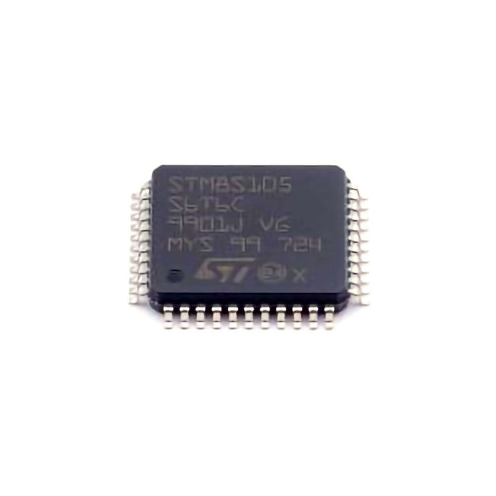
The STM8S105S6T6C is an 8-bit microcontroller from STMicroelectronics, part of the STM8S family. It is known for its Power efficiency, small form factor, and high performance in a variety of embedded applications. However, as with any complex system, engineers and developers can run into issues during development or deployment. Whether you’re working on a new project or troubleshooting an existing design, knowing how to diagnose and solve problems can save time and effort.
Key Features of the STM8S105S6T6C
Before diving into troubleshooting techniques, it’s essential to understand the key features of the STM8S105S6T6C microcontroller:
Core: STM8S105S6T6C is based on the 8-bit STM8 core, offering low power consumption and a wide range of peripheral options.
Memory : It has 8KB Flash memory, 1KB RAM, and 512B EEPROM, making it ideal for a variety of embedded applications.
Peripherals: The chip includes an array of peripherals, such as UART, I2C, SPI, timers, analog-to-digital converters (ADC), and more.
Operating Voltage: It operates at voltages ranging from 2.95V to 5.5V, making it versatile for various voltage levels in embedded systems.
Clock Speed: The MCU runs at a frequency of up to 16 MHz, providing a balance of power and speed.
With its combination of features, the STM8S105S6T6C is highly versatile for applications like motor control, consumer electronics, and industrial automation. However, like all microcontrollers, it may present some challenges that need addressing.
Common Issues with the STM8S105S6T6C
Power Supply Problems
Power issues are one of the most common causes of malfunction in embedded systems. An unstable or incorrect power supply can cause erratic behavior or failure to boot.
Solution:
Ensure that the voltage supplied to the MCU matches the specifications in the datasheet (typically 3.3V to 5V).
Check the power supply integrity with an oscilloscope to ensure there are no voltage spikes, drops, or noise.
Use decoupling capacitor s near the power pins of the microcontroller to reduce noise and stabilize the voltage.
Clock Issues
The STM8S105S6T6C uses an internal clock, but it can also be configured to use an external crystal or resonator. Incorrect clock configurations can prevent the MCU from starting up correctly or cause instability during operation.
Solution:
Double-check the clock configuration in the firmware to ensure the system clock is correctly set.
If using an external oscillator, verify the connections and the integrity of the external crystal. Ensure that the oscillator circuit is designed correctly.
Use an oscilloscope to measure the clock signal to verify proper oscillation.
Incorrect Reset Behavior
If the STM8S105S6T6C doesn’t boot up properly or constantly resets, this could indicate issues with the reset circuitry or software initialization.
Solution:
Check the NRST pin for correct voltage levels. Ensure it is not floating and has a proper pull-up resistor.
Review the firmware initialization sequence to ensure that the MCU is correctly configured and that no faulty software routines are causing the resets.
If using an external reset IC, verify the connections and behavior of the reset circuit.
Peripheral Configuration Issues
The STM8S105S6T6C includes a range of peripherals (e.g., UART, I2C, SPI, ADC, timers), and misconfiguring these peripherals can cause communication problems or malfunctioning devices.
Solution:
Carefully check the initialization code for each peripheral. Ensure that clocking, pins, and interrupt settings are correctly configured.
Use debugging tools to monitor the initialization sequence and identify where the configuration goes wrong.
For communication peripherals like UART or SPI, use a logic analyzer to monitor the signal integrity and ensure proper data transmission.
Watchdog Timer Issues
The STM8S105S6T6C comes with an integrated watchdog timer that can reset the MCU in case of software failure. However, incorrect watchdog configuration can result in the MCU being reset unintentionally or failing to reset when needed.
Solution:
Check the watchdog settings in the firmware. Ensure that it is properly configured to either reset the system or prevent unnecessary resets.
Review the software logic to ensure the watchdog is being regularly fed (i.e., cleared) to avoid unnecessary resets.
If the watchdog is triggering unexpectedly, debug the firmware to ensure that no infinite loops or blocking operations are preventing the watchdog from being cleared.
Hardware Troubleshooting Tips
Sometimes, the problem is not in the software but in the hardware design. Here are a few common hardware-related issues and troubleshooting tips:
Incorrect Pin Connections
Verify that all pins are connected properly, particularly for peripherals like I2C, SPI, and GPIOs. Incorrect pin connections can cause the system to behave erratically.
Grounding Issues
Improper grounding or floating ground pins can lead to noise or instability in the MCU. Ensure that the ground pins are well-connected and have a solid return path.
Inadequate Power Decoupling
Ensure that the STM8S105S6T6C has adequate power decoupling capacitors (typically 0.1µF or 1µF) close to the power pins to prevent noise or voltage spikes.
Advanced Troubleshooting Techniques and Best Practices
In Part 1, we explored common issues with the STM8S105S6T6C and some basic troubleshooting methods. Now, let’s dive deeper into advanced troubleshooting techniques and best practices that can help you resolve more complex problems.
Using Debugging Tools Effectively
In-Circuit Debugger (ICD)
An in-circuit debugger is one of the most powerful tools for troubleshooting STM8-based systems. The ST-LINK/V2 debugger is compatible with STM8S microcontrollers and allows real-time debugging, breakpoints, and step-through execution.
Solution:
Use breakpoints in the firmware to halt execution at critical points and inspect variables, registers, and memory values.
Use the debugger to trace the execution flow of your program. This will help identify where the code diverges from the expected behavior.
Monitor peripheral states in real time to see how the configuration affects the system.
Oscilloscope
An oscilloscope is invaluable for diagnosing clock, power, and signal integrity issues. For example, if you suspect a clock issue, an oscilloscope can help you verify whether the clock signal is present and clean.
Solution:
Use the oscilloscope to inspect the power supply line for noise, ripple, or instability.
Check the signals on communication lines (e.g., UART, SPI, I2C) to ensure they are transmitted correctly.
Measure the clock signal to verify that it meets the MCU’s specifications.
Logic Analyzer
When working with communication peripherals like UART, SPI, or I2C, a logic analyzer is essential for ensuring that data is being sent and received correctly.
Solution:
Use the logic analyzer to capture the waveforms on the communication lines. Verify that the data follows the correct protocol and that there are no transmission errors.
Analyze timing issues, such as slow clock speeds or data being transmitted too quickly for the peripheral to handle.
Firmware Debugging Strategies
Simplify the Code
Sometimes, issues arise from overly complex or poorly structured code. If your system isn’t working as expected, consider simplifying your firmware to the bare minimum to verify basic functionality.
Solution:
Comment out non-essential code and focus on the core functionality (e.g., basic LED blinking or simple serial communication) to test the hardware and peripheral setups.
Gradually reintroduce more complex features to identify where the issue occurs.
Check Interrupts and Timers
Incorrectly configured interrupts or timers can cause timing issues, missed events, or erratic behavior. Double-check your interrupt vectors, priorities, and timer settings to ensure everything is configured correctly.
Solution:
Verify interrupt enablement and ensure that interrupt vectors are correctly mapped.
If using timers for time-sensitive operations, ensure that they are correctly initialized and that their interrupt handlers are implemented properly.
Best Practices for Preventing Common Issues
Thoroughly Review the Datasheet
The STM8S105S6T6C datasheet is a comprehensive document that details the microcontroller’s features, electrical characteristics, and recommended operating conditions. Always refer to the datasheet before making design decisions to avoid potential issues.
Use Development Kits and Evaluation Boards
Development kits and evaluation boards are an excellent way to prototype and test your design before committing to a custom PCB. These boards are pre-tested, which can help you avoid common hardware issues in the early stages of development.
Utilize Community Forums and Resources
If you encounter persistent problems, there are numerous online communities and resources dedicated to STM8 and embedded development. Platforms like STMicroelectronics’ community forum, StackOverflow, and EEVBlog are great places to seek advice and share troubleshooting tips.
Conclusion
The STM8S105S6T6C microcontroller is a robust and efficient solution for many embedded applications, but like any complex system, it may present challenges during development. By following the troubleshooting tips and best practices outlined in this article, you can effectively diagnose and resolve common issues such as power supply problems, clock misconfigurations, and peripheral errors. Utilizing debugging tools like ICDs, oscilloscopes, and logic analyzers, along with reviewing datasheets and firmware code carefully, can streamline the development process and reduce downtime.
With patience, persistence, and the right tools, most issues with the STM8S105S6T6C can be identified and corrected, ensuring your project runs smoothly and efficiently.
If you’re looking for models of commonly used electronic components or more information about STM8S105S6T6C datasheets, compile all your procurement and CAD information in one place.
( Partnering with an electronic component supplier) sets your team up for success, ensuring that the design, production and procurement processes are streamlined and error-free. (Contact us) for free today.


